Image forming apparatus and image forming method
a technology of image forming and forming method, which is applied in the direction of printing, other printing apparatus, etc., can solve the problems of deposition interference between droplets on recording media, degradation of image, color smearing, etc., to prevent unsatisfactory ejection, prevent permeation smearing, color smearing, and increase the viscosity of droplets.
- Summary
- Abstract
- Description
- Claims
- Application Information
AI Technical Summary
Benefits of technology
Problems solved by technology
Method used
Image
Examples
first embodiment
; Overall Configuration of Inkjet Recording Apparatus
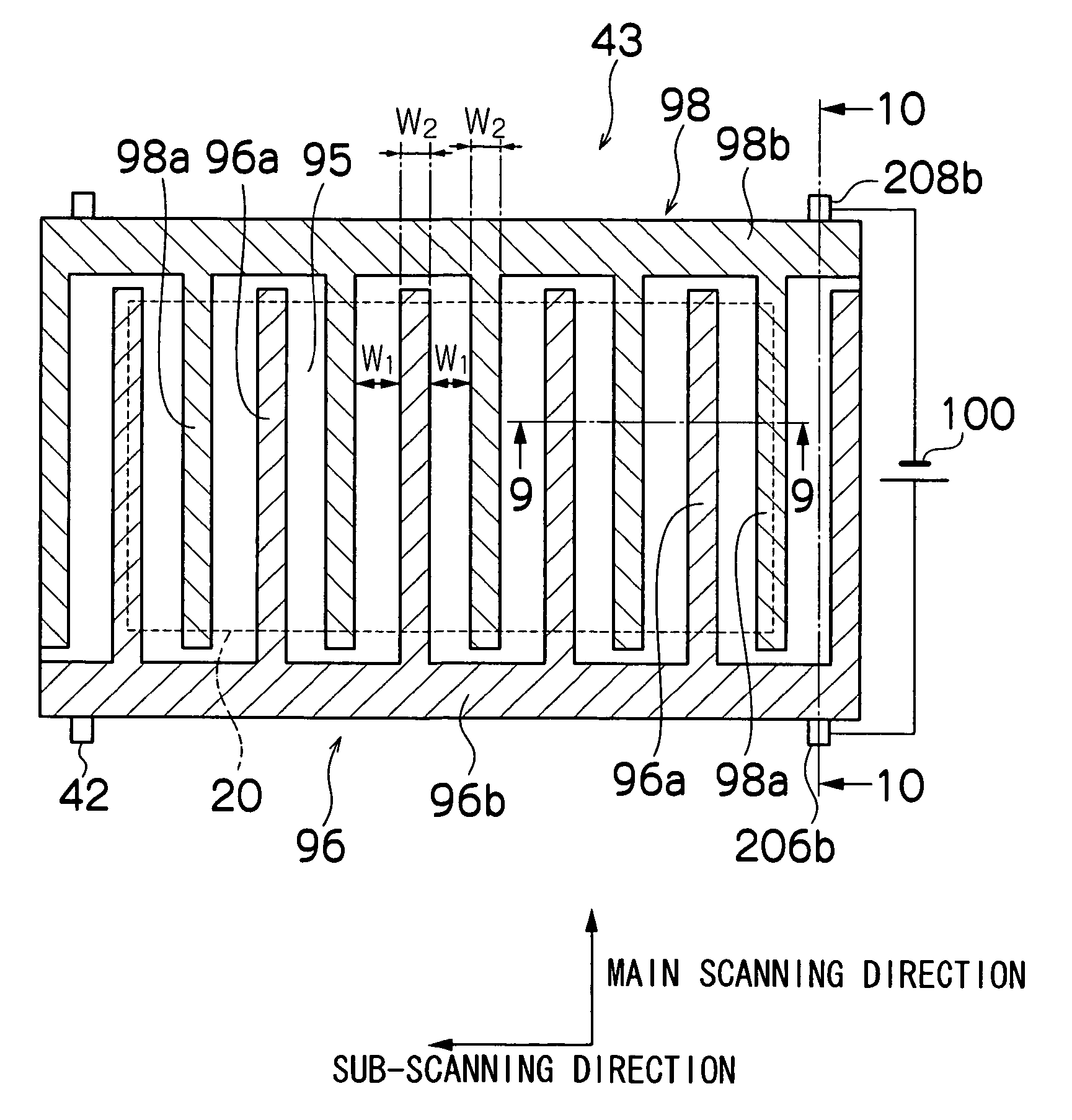
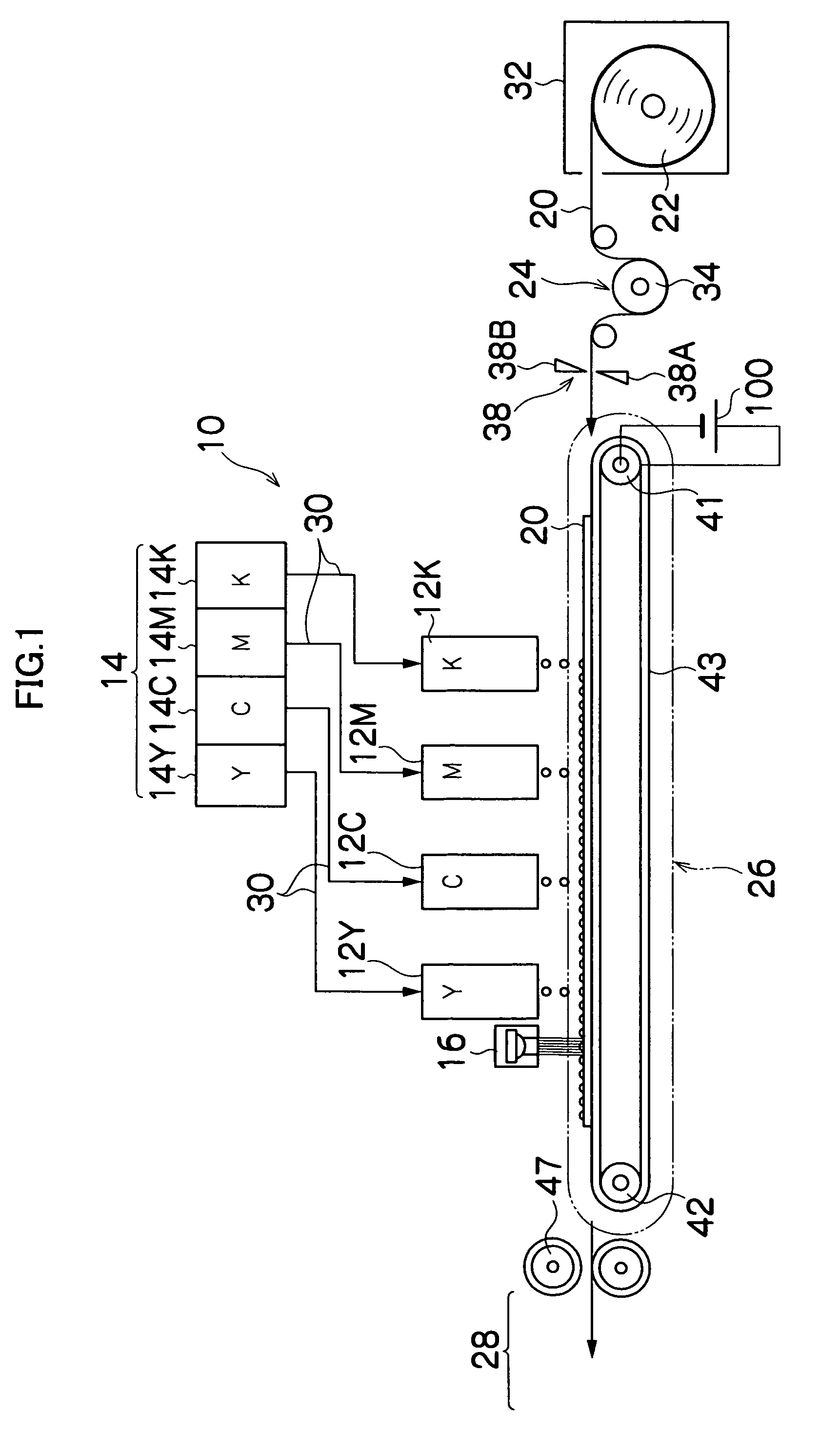
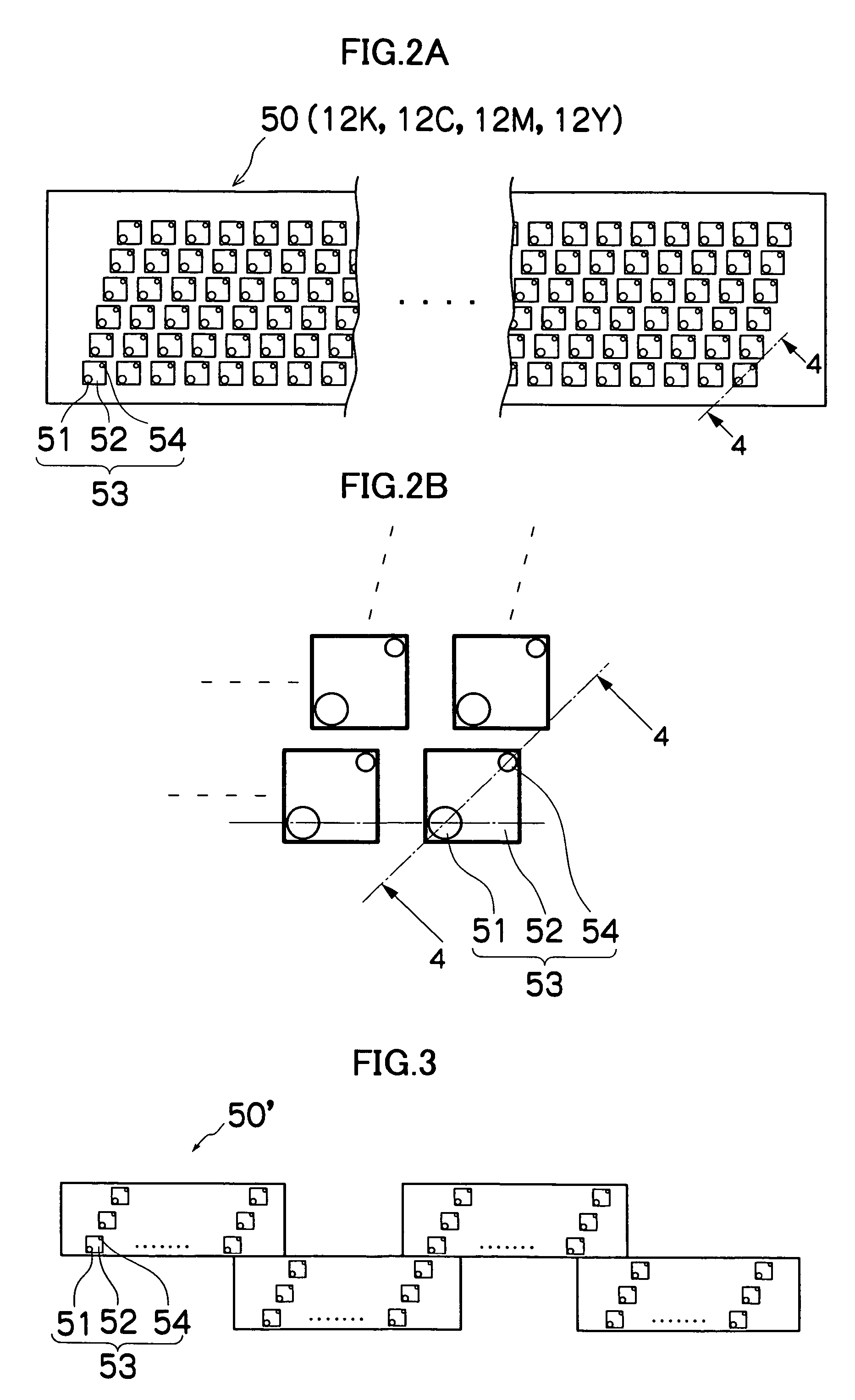
[0061]FIG. 1 is a general schematic drawing of an inkjet recording apparatus 10 according to a first embodiment of the present invention. As shown in FIG. 1, the inkjet recording apparatus 10 comprises a plurality of print heads 12K, 12M, 12C, and 12Y provided for each color of ink; an ink storing and loading unit 14 that stores the ink (in the present embodiment, UV-curing ink that has electro Theological effects) to be supplied to the print heads 12K, 12M, 12C, and 12Y; an ultraviolet source (UV source) 16 disposed on the downstream side in the conveyance direction of the print head 12Y (to the left hand in FIG. 1); a medium supply unit 22 that supplies a medium (recording medium) 20; a decurling process unit 24 that removes the curls in the medium 20; a conveying unit 26 that is disposed facing the nozzle surfaces (ink ejection surfaces) of the print heads 12K, 12M, 12C, and 12Y and also facing the light emission surface of the...
second embodiment
[0168]Next, the second embodiment of the present invention will be described.
[0169]FIG. 15 is a plan view showing schematic configuration of an electrode layer according to a second embodiment of the present invention. FIG. 16 is a cross-sectional view of the position 16-16 in FIG. 15, for depicting the relationship between the print head 50 and the ink droplets on the medium 20. In FIGS. 15 and 16, identical reference numerals denote parts that are common to FIGS. 11 and 12, and description thereof is omitted here.
[0170]In the electrode layer 92 (see FIG. 9) of the present embodiment, small and substantially square electrode pieces with a positive charge (hereinafter referred to as positive electrode pieces) 96c and electrode pieces with a negative charge (hereinafter referred to as negative electrode pieces) 98c are disposed in the matrix form alternating in the main scanning direction and the sub-scanning direction, as shown in FIG. 15.
[0171]A positive common wire 107 and a negat...
third embodiment
[0181]Next, the third embodiment of the present invention will be described.
[0182]FIG. 18 is a schematic drawing showing the principal component of the inkjet recording apparatus according to the third embodiment of the present invention. In FIG. 18, identical reference numerals denote parts that are common to FIG. 1, and description thereof is omitted here.
[0183]As shown in FIG. 18, a roller-shaped electrode unit 302 is supported by a support shaft 304, and is configured to be capable of rotating around the support shaft 304 in the direction shown as an arrow in FIG. 18. The print heads 12K, 12M, 12C, and 12Y are disposed in order from upstream to downstream in the rolling direction of the roller-shaped electrode unit 302, and a UV source 16 is provided downstream of the print head 12Y.
[0184]Though not shown in FIG. 18, the roller-shaped electrode unit 302 is composed of a support layer 90, an electrode layer 92, and a low-conductivity layer 94 (see FIG. 9), similar to the belt-sha...
PUM
 Abstract
Description
Claims
Application Information
 - R&D
- Intellectual Property
- Life Sciences
- Materials
- Tech Scout
- Unparalleled Data Quality
- Higher Quality Content
- 60% Fewer Hallucinations
Browse by: Latest US Patents, China's latest patents, Technical Efficacy Thesaurus, Application Domain, Technology Topic, Popular Technical Reports.
© 2025 PatSnap. All rights reserved.Legal|Privacy policy|Modern Slavery Act Transparency Statement|Sitemap|About US| Contact US: help@patsnap.com


