Compressor unit

a compressor unit and unit body technology, applied in the direction of positive displacement liquid engine, piston pump, liquid fuel engine, etc., can solve the problems of wear to itself and the stator, and the inability of the known partition to absorb high pressure differences between the stators

Inactive Publication Date: 2009-08-18
SIEMENS AG
View PDF18 Cites 39 Cited by
  • Summary
  • Abstract
  • Description
  • Claims
  • Application Information

AI Technical Summary

Benefits of technology

[0007]In particular, it is an object of the invention to provide a compressor unit, provided with a partition, which is able to absorb relatively high pressure differences and which does not cause any wear to itself and / or to the stator.
[0009]The stator space is delimited by a wall section, surrounding the stator, of the common housing of the compressor unit, a gastight partition and at least one end wall, which connects the partition in a gastight manner to the housing of the compressor unit. With this, the housing of the compressor unit may be shaped in such a manner that it fulfils the function of an end wall on one or two sides of the stator. The gastight partition not only keeps the stator space free of the gas, but also ensures that a different pressure can prevail in the stator space compared to the working pressures which are present in the compressor. The gastight partition extends freely between the stator and the rotor, with the result that it does not touch the stator and the rotor. This orientation of the partition has the advantage that the stator and the partition can expand and contract independently of one another under the influence of temperature changes without scraping along one another, which could otherwise cause wear. The partition is made from a material which is sufficiently strong for the deformation of the partition resulting from tensile stress which is produced from the working pressure of the compressor to be sufficiently low for the partition to remain clear of both the stator and the rotor.
[0011]More particularly, the partition comprises an erosion-resistant layer on the rotor side. This layer protects the partition from erosion by the gas itself, by any aggressive and abrasive components in the gas and / or by high temperatures of the gas.

Problems solved by technology

Firstly, the partition may cause wear to itself and to the stator.
Secondly, the known partition is unable to absorb high pressure differences between the stator space and the rotor space.

Method used


Image

  • Compressor unit
  • Compressor unit
  • Compressor unit

Examples


Embodiment Construction

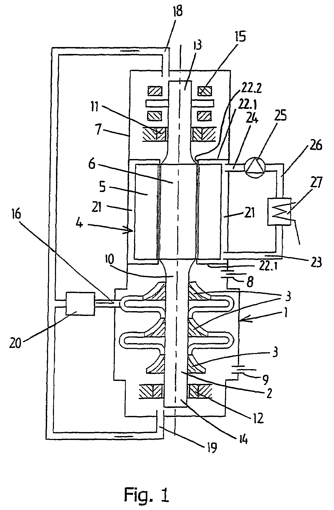
[0022]The compressor unit illustrated in FIG. 1 comprises a centrifugal compressor 1 for compressing a gas, for example process gas, having a rotor 2 with one or more, in this case three, compressor impellers 3 and an electric motor 4 having a stator 5 and a rotor 6 for driving the rotor 2 of the compressor. The compressor 1 and the electric motor 4 are accommodated in a common gastight housing 7 which is provided with a gas inlet 8 and a gas outlet 9.

[0023]The rotor 2 of the compressor 1 and the rotor 6 of the electric motor 4 are arranged on a common rotor shaft 10 comprising one single unit. The rotor shaft 10 is mounted in two magnetic radial bearings 11 and 12, which are each arranged in the vicinity of an end 13 and 14, respectively, of the rotor shaft 10, and a magnetic axial bearing 15 arranged in the vicinity of the radial bearing 11.

[0024]The compressor unit is provided with a cooling system for cooling the magnetic bearings 11, 12, 15 and the rotor 6 of the electric motor...


PUM


Abstract

A compressor unit including a centrifugal compressor for compressing a gas and an electric motor with a stator and a rotor for driving the compressor. The compressor and the electric motor are accommodated in a common gastight housing, provided with a gas inlet and a gas outlet.The stator is accommodated in a separate stator space which is delimited by a wall section, surrounding the stator, of the housing, a gastight partition which extends freely between the stator and the rotor of the electric motor, and at least one end wall which extends between the partition and the housing of the compressor unit.The partition is of a material of such high strength that it remains clear of the stator and the rotor under working pressures of the gas.

Description

CROSS-REFERENCE TO RELATED APPLICATION[0001]This is a U.S. National Phase application of PCT / NL2003 / 000692, which PCT application claims priority of Dutch patent application number 1021656 filed Oct. 15, 2002, both herein incorporated by reference.FIELD OF THE INVENTION[0002]The invention relates to a compressor unit having a common housing for electric motor and compressor.BACKGROUND OF THE INVENTION[0003]A compressor unit is known from U.S. Pat. No. 3,960,468, which discloses a compressor unit for compressing a gas. The compressor unit comprises a centrifugal compressor and an electric motor. The electric motor comprises a stator and a rotor, the rotor driving the compressor. The compressor and the electric motor are accommodated in a common gastight housing which is provided with a gas inlet and a gas outlet.[0004]In the compressor unit shown in FIG. 1 of U.S. Pat. No. 3,960,468, there is a thin partition between the space in which the stator is located and the space in which the...

Claims


Application Information

Patent Timeline
Patent Type & Authority Patents(United States)
IPC IPC(8): F04B35/04F04D25/06F04D29/02H02K5/128
CPCF04D25/0606H02K5/128F04D29/023H02K2005/1287F05D2300/43F05D2300/603F05D2230/31F04D13/0626
Inventor BODE, RALF HEINRICHMECKING, KLAUS
Owner SIEMENS AG
Why Eureka
Try Eureka