Surface mount right angle connector including strain relief and associated methods

a right angle connector and connector technology, applied in the field of radio frequency and microwave circuits and systems, can solve the problems of reducing the usable bandwidth of the cable, reducing the usable bandwidth, and requiring a large space and volume, so as to achieve sufficient cable strain relief and increase the usable bandwidth

Active Publication Date: 2009-08-18
HARRIS CORP
View PDF24 Cites 50 Cited by
  • Summary
  • Abstract
  • Description
  • Claims
  • Application Information

AI Technical Summary

Benefits of technology

[0018]Thus, with the present approach, a surface mount connector may be provided for a PCB of a high frequency or broadband (DC—20 GHz) electronic device that includes a right-angle pin launch onto the PCB planar surface conductor with sufficient cable strain relief. The radially extending main recess in the header, the dielectric material

Problems solved by technology

Disadvantages of this approach include the relatively large space and volume requirements, and the requirement that the transition be

Method used


Image

  • Surface mount right angle connector including strain relief and associated methods
  • Surface mount right angle connector including strain relief and associated methods
  • Surface mount right angle connector including strain relief and associated methods

Examples


Embodiment Construction

[0024]The present invention will now be described more fully hereinafter with reference to the accompanying drawings, in which preferred embodiments of the invention are shown. This invention may, however, be embodied in many different forms and should not be construed as limited to the embodiments set forth herein. Rather, these embodiments are provided so that this disclosure will be thorough and complete, and will fully convey the scope of the invention to those skilled in the art. Like numbers refer to like elements throughout.

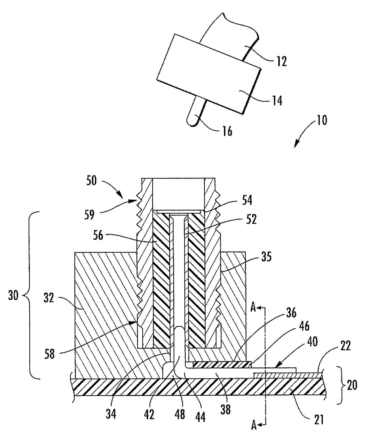
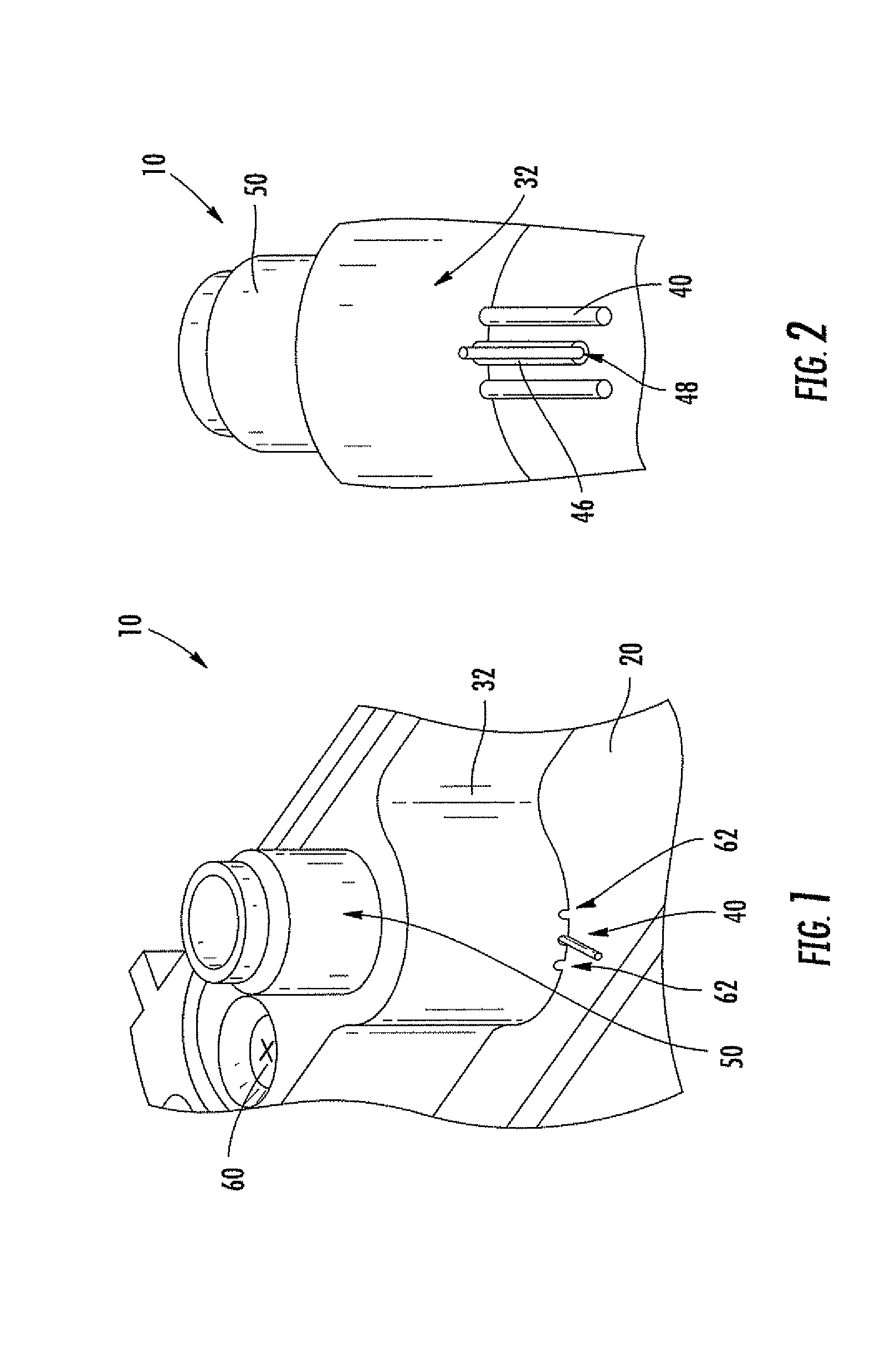
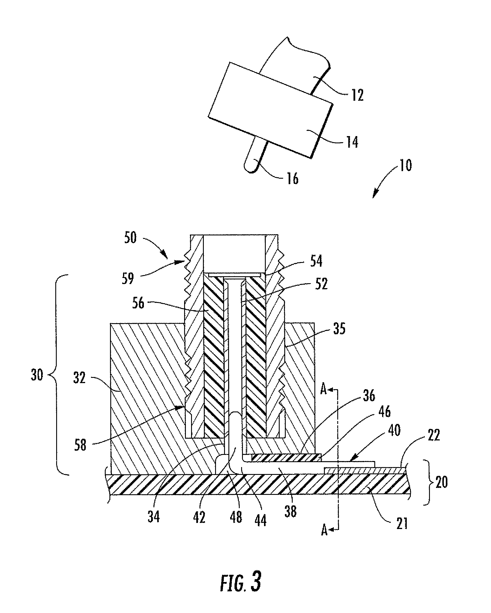
[0025]Referring initially to FIGS. 1-5, an electronic device 10, e.g. for operation in the RF and microwave frequency ranges, that includes a surface mount right-angle or orthogonal transition from a cable 12 to a planar surface conductor 22 with sufficient strain relief will now be described. The electronic device 10 includes a printed circuit board (PCB) having a dielectric layer 21 and an electrically conductive layer thereon defining a PCB planar surfa...


PUM


Abstract

An electronic device includes a printed circuit board (PCB) including a planar surface conductor, e.g. such as a microstrip transmission line or coplanar transmission waveguide. A surface mount connector portion is mounted to the PCB and includes an electrically conductive header having a cylindrical bore extending therethrough and aligned normal to the PCB, the electrically conductive header also having a radially extending main recess in a bottom end thereof in communication with the cylindrical bore. An electrically conductive pin extends through the main recess and has a first end coupled to the planar surface conductor, a second end within the cylindrical bore and a bend therebetween. A dielectric is in the main recess between the pin and adjacent portions of the electrically conductive header, and an interconnect is within the cylindrical bore and includes a center conductive channel to receive the second end of the pin.

Description

GOVERNMENT LICENSE RIGHTS[0001]U.S. Government has a paid-up license in this invention and the right in limited circumstances to require the patent owner to license others on reasonable terms.FIELD OF THE INVENTION[0002]The present invention relates to the field of radio frequency (RF) and microwave circuits and systems, and, more particularly, to surface mount connectors for use in RF and microwave circuits and systems, and related methods.BACKGROUND OF THE INVENTION[0003]“Printed circuit boards” (PCBs) or “printed wiring boards” (PWBs) are frequently interconnected with one another using coaxial cables in high frequency devices, circuits and subsystems, such as those operating at radio frequency (RF) and microwave frequency ranges. Coaxial connectors at an interface between a PCB and the coaxial cable allow a PCB to be connected and disconnected during assembly and / or testing, as well as for maintenance and replacement purposes once the PCB has been deployed. A variety of classes ...

Claims


Application Information

Patent Timeline
IPC IPC(8): H01R9/05
CPCH01R24/50H01R12/716H01R2103/00
Inventor DODSON, JAMES BRADLEYRIVERS, NORMANHARRISON, GEORGE ALBERT
Owner HARRIS CORP
Why Eureka
Try Eureka