
Endoscopic treatment instrument, endoscopic treatment system and supporting adaptor

a technology of endoscopic treatment and adaptor, which is applied in the field of endoscopic treatment instruments and supporting adaptors, can solve the problems of limited diameter of the instrument which can be inserted into the forceps channel, and makes operation difficult for the operator, and achieves the effect of facilitating manipulation and reducing the time required for manipulation

Active Publication Date: 2009-08-18
OLYMPUS CORP
View PDF13 Cites 131 Cited by
  • Summary
  • Abstract
  • Description
  • Claims
  • Application Information

AI Technical Summary

Benefits of technology

[0011]It is configured in such a manner that an operator can change the arrangement of the plurality of sheaths with respect to the endoscope insertion part by changing a connecting state of the connecting member.
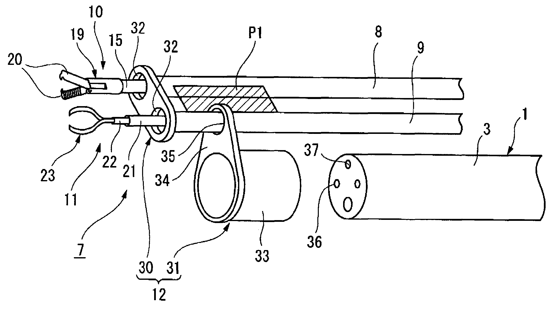
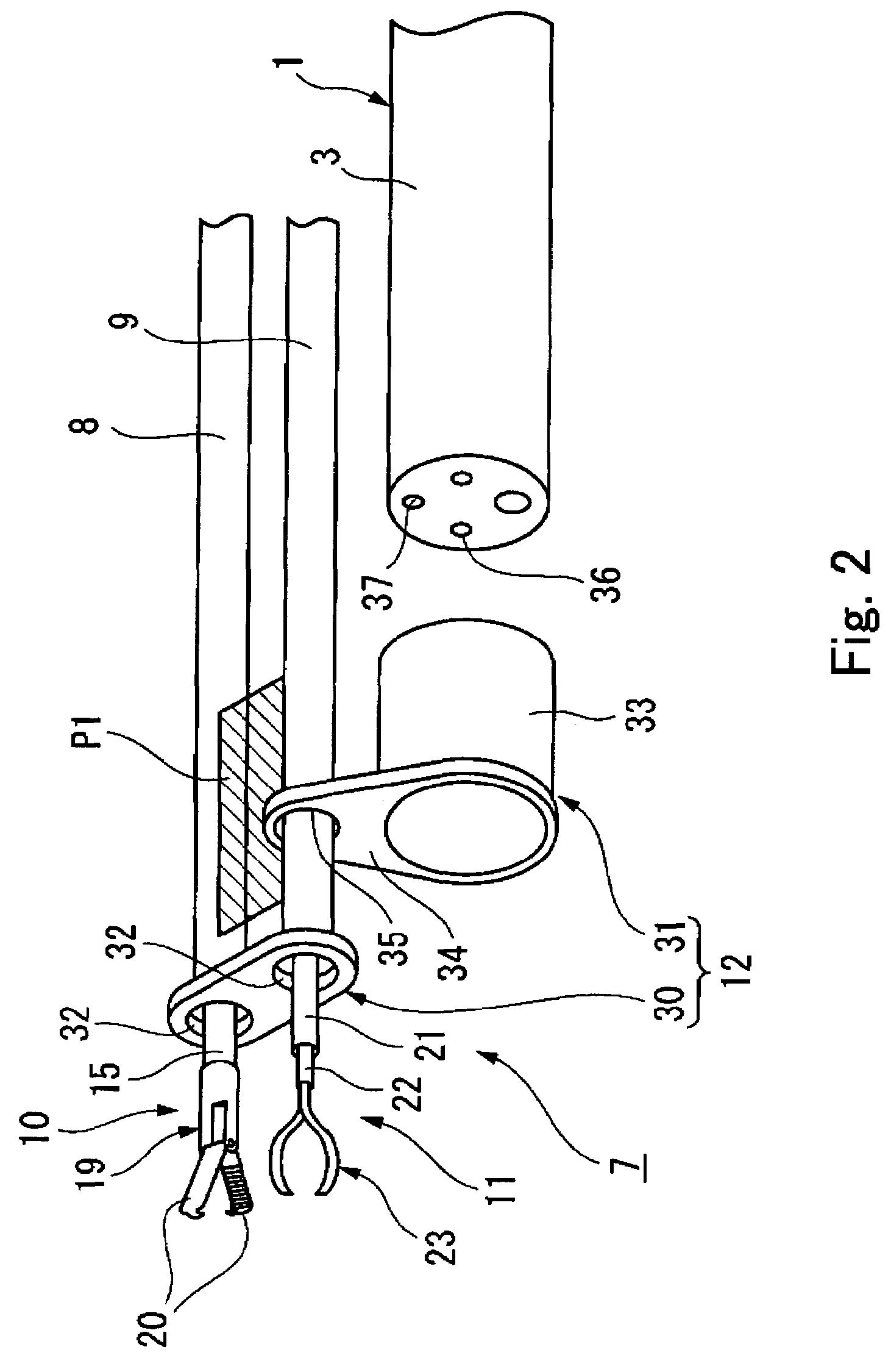
[0027]According to the invention, the endoscopic treatment instrument can be externally attached to the endoscope easily via the connecting member. Also, change of the arrangement of the plurality of elongated flexible sheaths with respect to the endoscope can be achieved, for example, by rotating the treatment instrument system while fixing the relative positional relation of the plurality of distal end treatment units by the supporting member. Therefore, the arrangement of the distal end treatment units on a display of the endoscope can be changed, for example, without re-inserting the treatment units into the sheaths. Therefore, the manipulation thereof is facilitated, and hence the time required for manipulation can be reduced.

Problems solved by technology

As the diameter of a forceps channel formed in the endoscope is small, the diameter of the instrument which can be inserted into the forceps channel is limited.
In such cases, when the entire endoscope is rotated in order to exchange the distal end treatment units between the left side and the right side, the field of view of the endoscope is also rotated correspondingly, and hence it makes operation difficult for an operator.

Method used


Image

  • Endoscopic treatment instrument, endoscopic treatment system and supporting adaptor
  • Endoscopic treatment instrument, endoscopic treatment system and supporting adaptor
  • Endoscopic treatment instrument, endoscopic treatment system and supporting adaptor

Examples


first embodiment

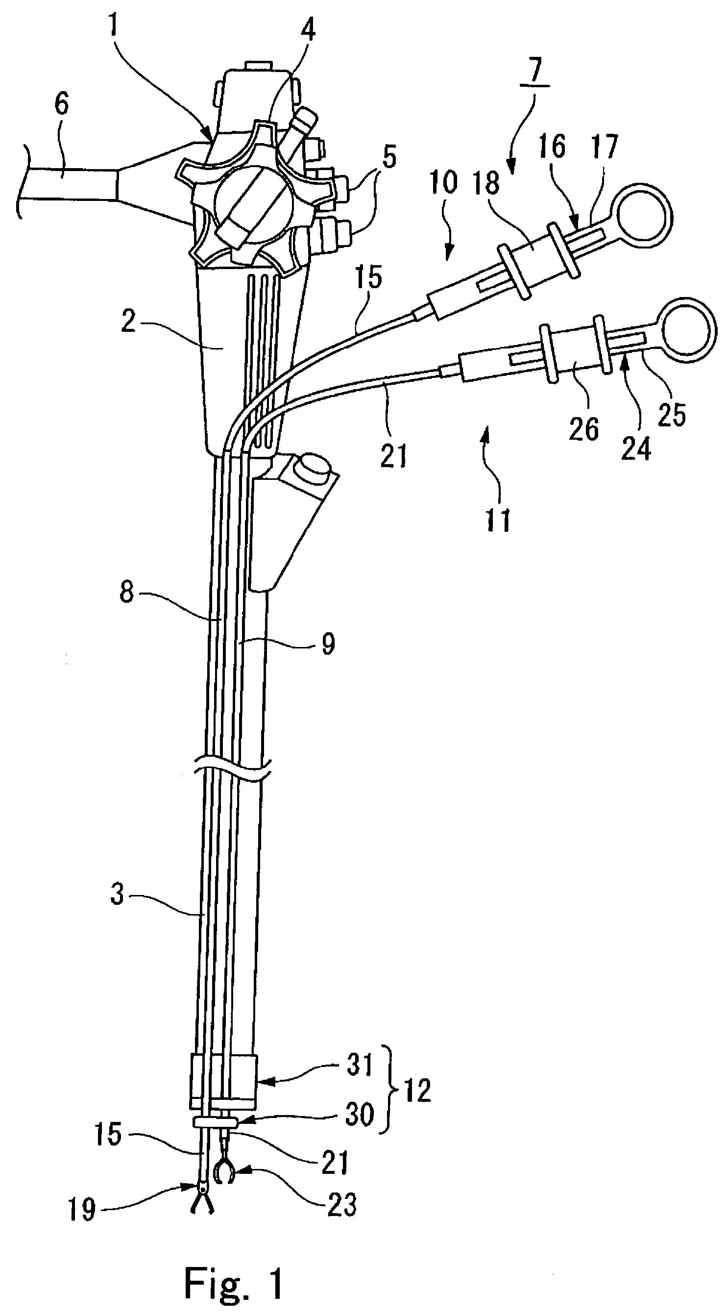
[0056]FIG. 1 shows a state in which an endoscopic treatment instrument is mounted to an endoscope.

[0057]The endoscope 1 is provided with an endoscope insertion part (hereinafter, referred to as insertion part) 3 at a distal end of an operating part 2 which is operated by an operator. The insertion part 3 has an elongated shape and has flexibility, and is provided with a CCD, an illumination means, and the like at a distal portion thereof. The operating part 2 includes a knob 4 for bending the distal portion of the insertion part 3, switches 5, a universal cord 6, and so on. The endoscope 1 in this configuration is externally attached with endoscopic treatment instruments (hereinafter referred to as the treatment instruments) 7 in a state of being inserted into two of first and second external channels 8, 9 as tubular members. The first external channel 8 and the second external channel 9 are flexible sheaths. The first external channel 8 and the second external channel 9 each are f...

second embodiment

[0078]In the second embodiment, the first and second external channels 8, 9 are detachably supported by the connecting member 54 so that the sheaths 60, 63 can be attached to the insertion part 3 with the relative arrangement fixed. In addition, by rotating the supporting member 30 about its own axis, the injection needle catheter 51 and the snare 52 can be attached to the connecting member 54 with the their positions being exchanged. Accordingly, the arrangement of the injection needle catheter 51 and the snare 52 can be reversed in the lateral direction. Therefore, it is not necessary to remove the sheaths 60, 63 from the external channels 8, 9 every time when exchanging the arrangement of the treatment instrument 50, and hence working efficiency is improved, and manipulation time can be reduced.

[0079]It is also possible to provide a plate-shaped magnet 65 connecting the two external channels 8, 9 as shown in FIG. 11. The sheath supporting section of the connecting member 54 compr...

third embodiment

[0080]Referring now to the drawings, a third embodiment will be described. The same parts as those in the above-described respective embodiments are represented by the same reference numerals, and redundant description will be omitted.

[0081]As shown in FIG. 12, a treatment instrument 70 includes a pinching forceps 73 provided with a pair of working units 71, 72 inserted into the two external channels 8, 9 respectively, and a supporting adaptor 74. The supporting adaptor 74 includes a supporting member 75 and a connecting member 76 which is detachably attached to the supporting member 75.

[0082]The supporting member 75 is formed with two through holes 77 so as to extend in parallel with each other at a predetermined distance, and the external channels 8, 9 are fixed so that the lumens thereof communicate with the through holes 77, respectively. In the supporting member 75, an upper surface 75a and a lower surface 75b which extend substantially in parallel with a plane passing through ...


PUM


Abstract

In an endoscopic treatment instrument having a plurality of sheaths, a supporting member for directly and indirectly supporting the plurality of sheaths, and a connecting member for directly / indirectly bringing the sheaths and an endoscope in a connected state are provided. The supporting member constrains a relative position of the plurality of sheaths and the connecting member can change the connecting state. Therefore, when an operator changes the connecting state of the connecting member, the positional relation of the endoscope and the plurality of sheaths can be changed, while the positional relation of the plurality of sheaths is still constrained. Accordingly, for example, left and right sheaths can be easily exchanged.

Description

CROSS-REFERENCE TO RELATED APPLICATION[0001]This application is based upon and claims the benefit of priority from prior Japanese Patent Application No. 2004-277028, filed Sep. 24, 2004, the entire contents of which is incorporated herein by reference.BACKGROUND OF THE INVENTION[0002]1. Field of the Invention[0003]The present invention relates to an endoscopic treatment instrument and a supporting adaptor to be used with an endoscope, and an endoscopic treatment system including the endoscope.[0004]2. Description of the Related Art[0005]An endoscopic treatment instrument (hereinafter, referred to as an instrument) is inserted into a body with an endoscope for carrying out a treatment for living organisms, and includes a distal treatment unit provided at a distal end of an elongated flexible sheath.[0006]As the diameter of a forceps channel formed in the endoscope is small, the diameter of the instrument which can be inserted into the forceps channel is limited. Therefore, when a lar...

Claims


Application Information

Patent Timeline
Patent Type & Authority Patents(United States)
IPC IPC(8): A61B1/00
CPCA61B1/00087A61B1/0014A61B19/26A61B1/018A61B2017/00296A61B17/00234A61B90/50
Inventor TAKEMOTO, SHOTAROYAMAMOTO, TETSUYAONUKI, YOSHIOKAWASHIMA, KOICHISAKAMOTO, YUJI
Owner OLYMPUS CORP
Learn More