Microscope with dual image sensors for rapid autofocusing

a microscope and image sensor technology, applied in the field of microscopes, can solve the problems of time delay that prevents rapid autofocusing, microscope may exhibit mechanical instability, and single reference point may lack sufficient information for accurate autofocusing

Active Publication Date: 2009-08-18
LEICA MICROSYSTEMS CMS GMBH
View PDF16 Cites 79 Cited by
  • Summary
  • Abstract
  • Description
  • Claims
  • Application Information

AI Technical Summary

Benefits of technology

[0009]In accordance with another embodiment, a digital optical microscope includes an objective lens, a beam splitter that splits light that is collected from a sample and passes through the objective lens into a primary light path and an auxiliary light path, a primary image sensor that generates a primary image of the sample with a primary pixel count at a primary frame rate using the primary light path without using the auxiliary light path, an auxiliary image sensor that generates an auxiliary image of the sample with an auxiliary pixel count at an auxiliary frame rate using the auxiliary light path without using the primary light path, and a controller that adjusts a focal distance between the objective lens and the sample along an optical axis using the auxiliary image without using the primary image, thereby autofocusing the primary image on the sample using the auxiliary image sensor without using the primary image sensor. The primary image sensor generates the primary image in response to the autofocusing, the auxiliary pixel count is lower than the primary pixel count and the auxiliary frame rate is faster than the primary frame rate.
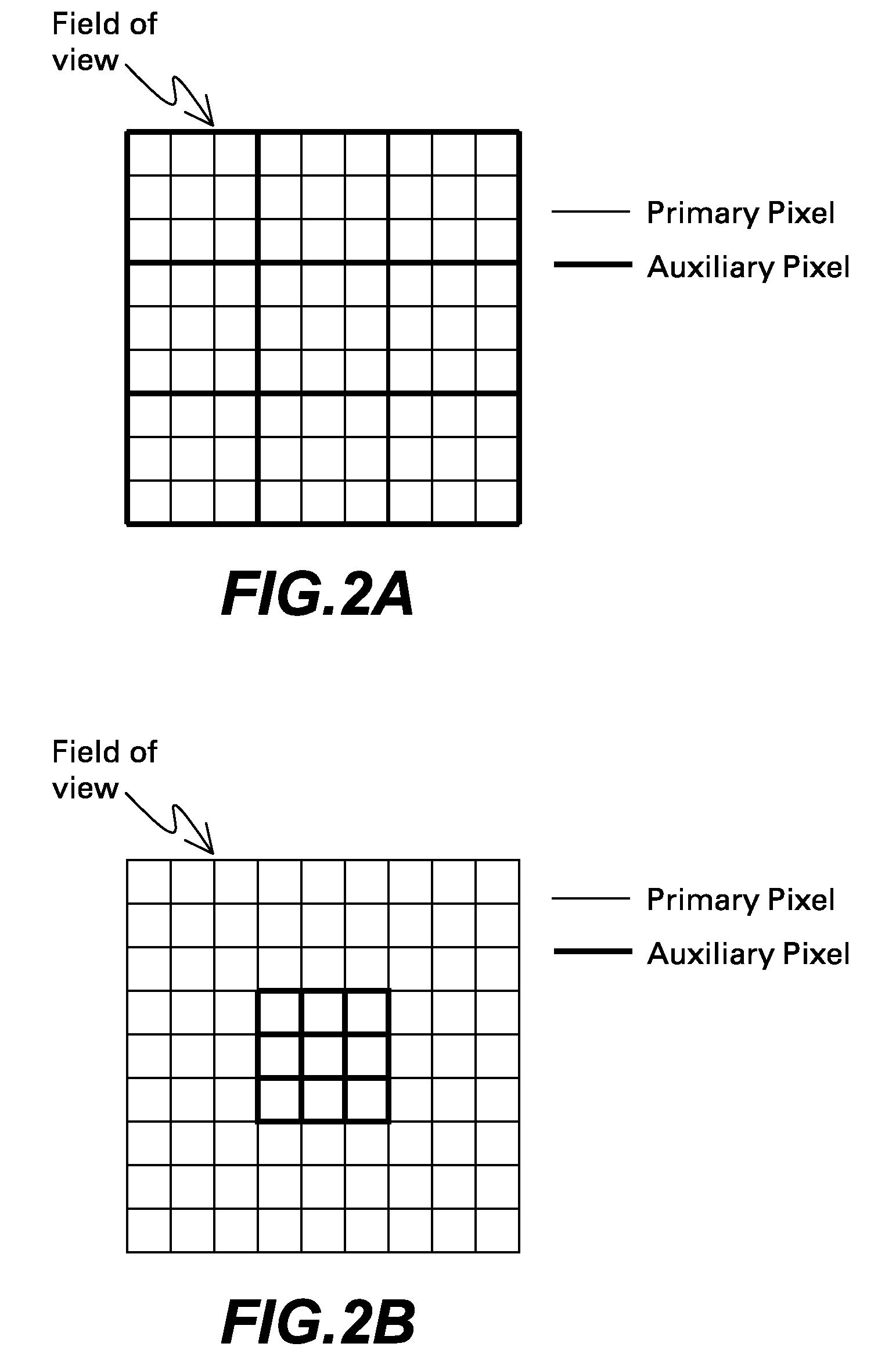
[0010]In accordance with a further embodiment, a digital optical microscope includes an objective lens with a field of view, a beam splitter that splits light that is collected from a sample at the field of view and passes through the objective lens into a primary light path and an auxiliary light path, a primary image sensor, an auxiliary image sensor and a controller. The primary image sensor generates first and second primary images of the sample using the primary light path without using the auxiliary light path, wherein the primary images each have a primary pixel count and are generated at a primary frame rate, the first primary image represents a first region of the sample at the field of view, the second primary image represents a second region of the sample at the field of view, and the regions are laterally offset. The auxiliary image sensor generates first, second and third auxiliary images of the sample using the auxiliary light path without using the primary light path, wherein the auxiliary images are generated while the field of view is at the second region and the auxiliary images each have an auxiliary pixel count and are generated at an auxiliary frame rate. The controller adjusts a lateral position between the objective lens and the sample to move the field of view from the first region to the second region and adjusts a focal distance between the objective lens and the sample along an optical axis to a selected focal distance using the auxiliary images without using the primary images, thereby autofocusing the second primary image on the sample using the auxiliary image sensor without using the primary image sensor, wherein the primary image sensor generates the first primary image while the controller moves the field of view from the first region to the second region, while the auxiliary image sensor generates the auxiliary images and while the controller adjusts the focal distance to the selected focal distance, the primary image sensor generates the second primary image in response to the autofocusing, the auxiliary pixel count is lower than the primary pixel count and the auxiliary frame rate is faster than the primary frame rate.

Problems solved by technology

Furthermore, the sample, coverslip and slide may have variable thickness, the sample may grow or move, and the microscope may exhibit mechanical instability, scanning stage misalignment and thermal expansion.
Although this approach provides rapid autofocusing, the single reference point may lack sufficient information for accurate autofocusing.
Although this approach provides accurate autofocusing, acquiring the multiple images may create time delays that prevent rapid autofocusing.

Method used


Image

  • Microscope with dual image sensors for rapid autofocusing
  • Microscope with dual image sensors for rapid autofocusing
  • Microscope with dual image sensors for rapid autofocusing

Examples


Embodiment Construction

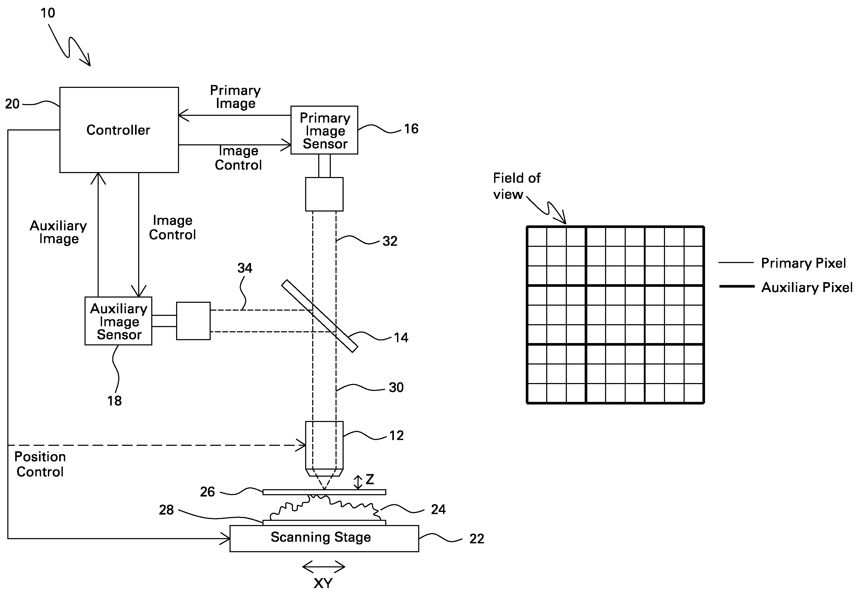
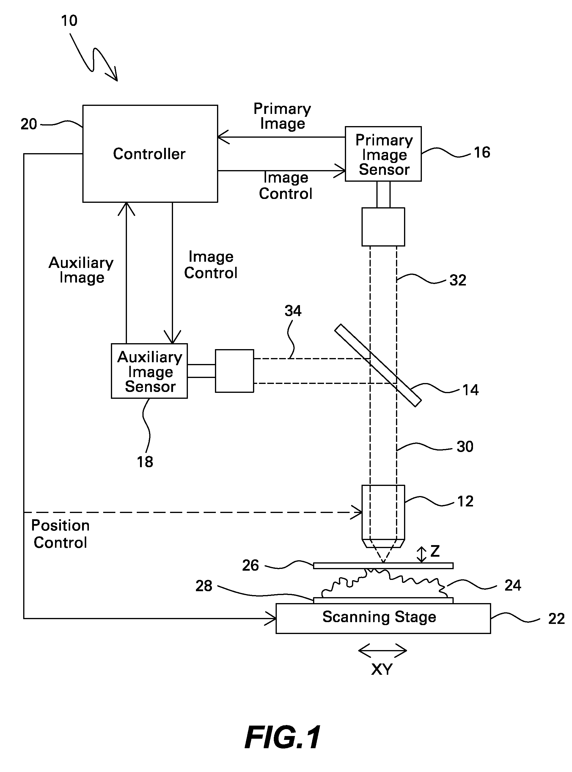
[0017]FIG. 1 illustrates one embodiment of a digital optical microscope 10 that includes objective lens 12, beam splitter 14, primary image sensor 16, auxiliary image sensor 18, controller 20 and scanning stage 22.

[0018]Sample 24 is disposed between coverslip 26 and slide 28, and sample 24, coverslip 26 and slide 28 are supported by scanning stage 22. Coverslip 26 and slide 28 may be transparent glass, while sample 24 may represent a wide variety of objects or samples including biological samples. For example, sample 24 may represent biopsy tissue such as liver or kidney cells. In a non-limiting example, such biopsy tissue samples may have a thickness that averages 5 microns and varies by several microns and may have a lateral surface area of approximately 15×15 millimeters, and.

[0019]Objective lens 12 is spaced from sample 24 by a focal distance that extends along an optical axis in the Z (vertical) direction, and objective lens 12 has a focal plane in the XY (lateral) directions. ...


PUM


Abstract

A digital optical microscope includes a primary image sensor that generates a primary image of a sample at a primary frame rate, an auxiliary image sensor that generates an auxiliary image of the sample at an auxiliary frame rate that is faster than the primary frame rate, and a controller that adjusts a focal distance between an objective lens and the sample along an optical axis in response to the auxiliary image, thereby autofocusing the primary image on the sample. The primary image sensor generates the primary image in response to the autofocusing.

Description

BACKGROUND[0001]Embodiments of the present invention relate to microscopes, and more particularly to a digital optical microscope that autofocuses on a sample.[0002]Digital optical microscopes are used to observe a wide variety of samples. Recently, a need has emerged to digitally record images of biological samples such as biopsy tissue on histopathologic slides for archiving, telepathology and rapid information retrieval. Although the samples are relatively thin, on the order of 5 microns, high power objective lenses with a numerical aperture greater than 0.5 typically have a depth of field that is even smaller. Furthermore, the sample, coverslip and slide may have variable thickness, the sample may grow or move, and the microscope may exhibit mechanical instability, scanning stage misalignment and thermal expansion.[0003]Therefore, in order to keep the sample in focus (along the optical axis in the Z direction) as the microscope scans the sample and relocates the field of view to...

Claims


Application Information

Patent Timeline
Patent Type & Authority Patents(United States)
IPC IPC(8): G02B27/16G02B27/40
CPCG02B21/365G02B21/245
Inventor YAZDANFAR, SIAVASHFILKINS, ROBERT JOHN
Owner LEICA MICROSYSTEMS CMS GMBH
Why Eureka
Try Eureka