
Method and arrangement for detecting moving objects with a radar

a technology of moving objects and radars, applied in the field of radar measurements, can solve the problems of fragmented information of smaller particles, mainly statistical, and unsuitable for measuring echoes from hard targets,

Inactive Publication Date: 2009-08-18
MELIORCOMP
View PDF16 Cites 46 Cited by
  • Summary
  • Abstract
  • Description
  • Claims
  • Application Information

AI Technical Summary

Benefits of technology

This approach significantly reduces the computational effort required for radar data analysis, enabling real-time processing of radar measurements with minimal loss in accuracy, thus facilitating efficient detection and tracking of moving objects like space debris.

Problems solved by technology

Large (>10 cm) objects have known orbits and are routinely monitored by the U.S. Space Surveillance Network, but information of the smaller particles is fragmentary and mainly statistical.
In order to remain in orbit an object must have a velocity of several kilometers per second in the Earth's coordinate system, which makes any such object potentially dangerous to satellites, manned spacecraft and other space-going vehicles.
However, these systems have been optimized for processing “soft” ionospheric reflections, and consequently are not well suited for measuring echoes from hard targets.
Therefore ionospheric echoes from individual pulses are uncorrelated and can only be added up in the power domain.
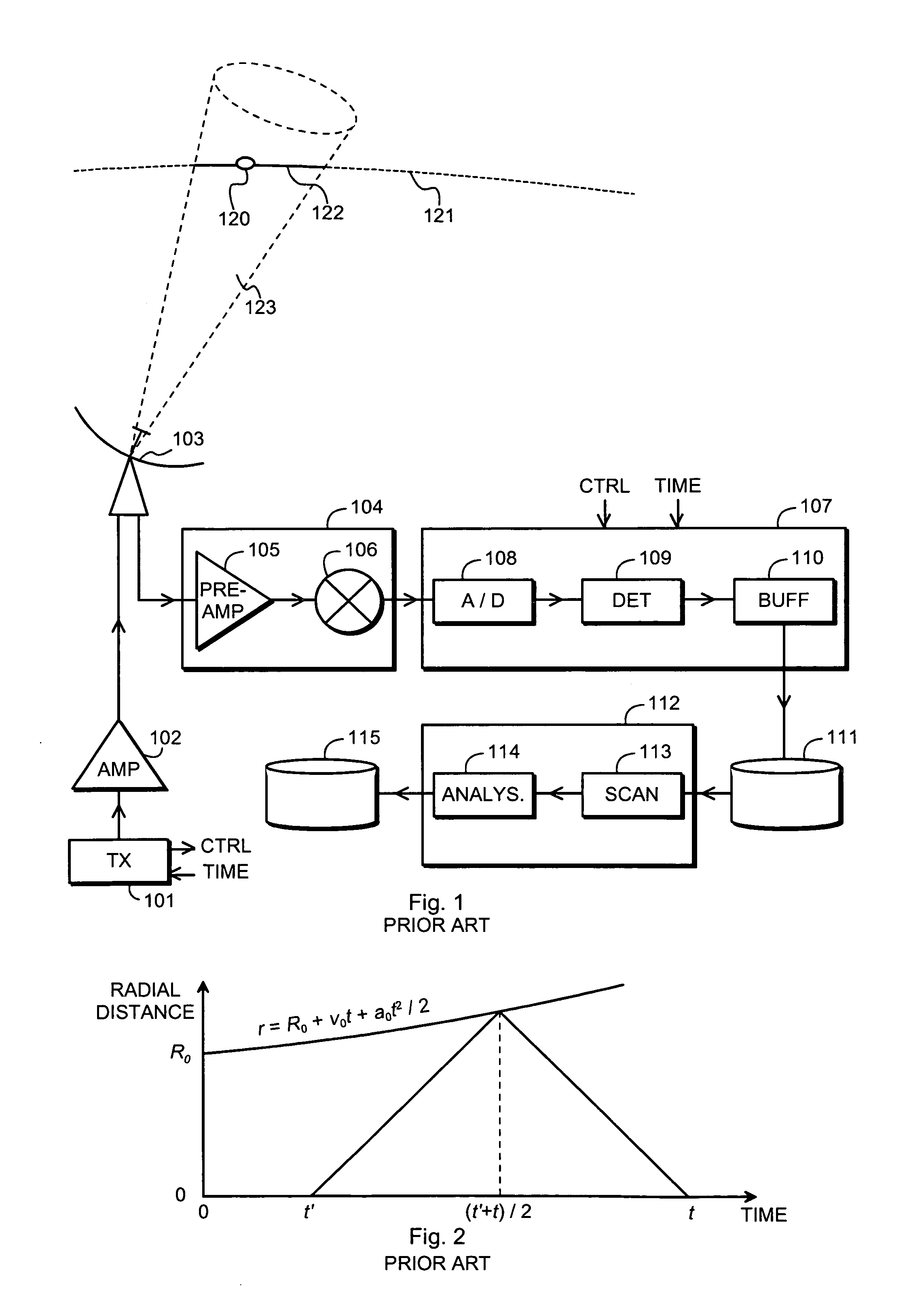
A problem of a measurement of the kind described above has previously been the vast amount of computing and data storage that is needed if measurements are to be made and results analysed in any reasonable time, or even real time.

Method used


Image

  • Method and arrangement for detecting moving objects with a radar
  • Method and arrangement for detecting moving objects with a radar
  • Method and arrangement for detecting moving objects with a radar

Examples


Embodiment Construction

Mathematical Derivation

[0026]The task of using a radar measurement to detect a distant moving object can be described simply as transmitting a known signal x(t) and finding the (best estimate of the) appropriate parameters of a hard target echo signal s(t) in the presence of gaussian noise γ(t). A received signal z(t) is a sum

z(t)=s(t)+γ(t)  (1)

and all mentioned quantities can be treated as complex-valued (detected) waveforms.

[0027]Using statistical inversion means that we use a parameterized model for the signal s(t) and find the most probable signal among a number of model signals, given the measured signal z(t).

[0028]Before making further assumptions about the model signals we only assume that a model signal depends linearly on the complex amplitude b and nonlinearly on some other parameters, which are collectively denoted by θ. In other words, our assumption about the correct, noise-free target echo signal has the form

s(t)=b·χ(θ;t).  (2)

[0029]We sample the received signal z(t) u...


PUM


Abstract

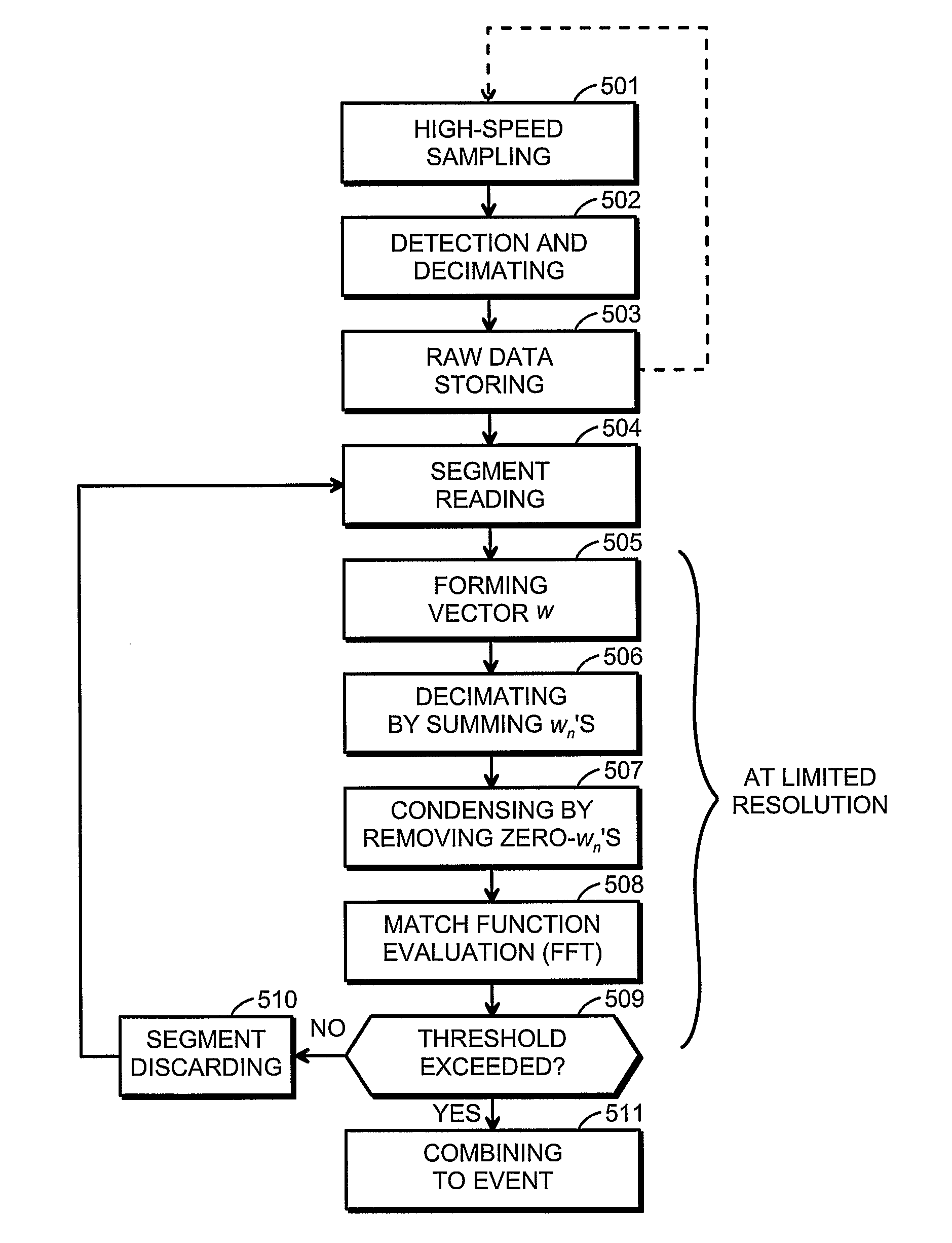
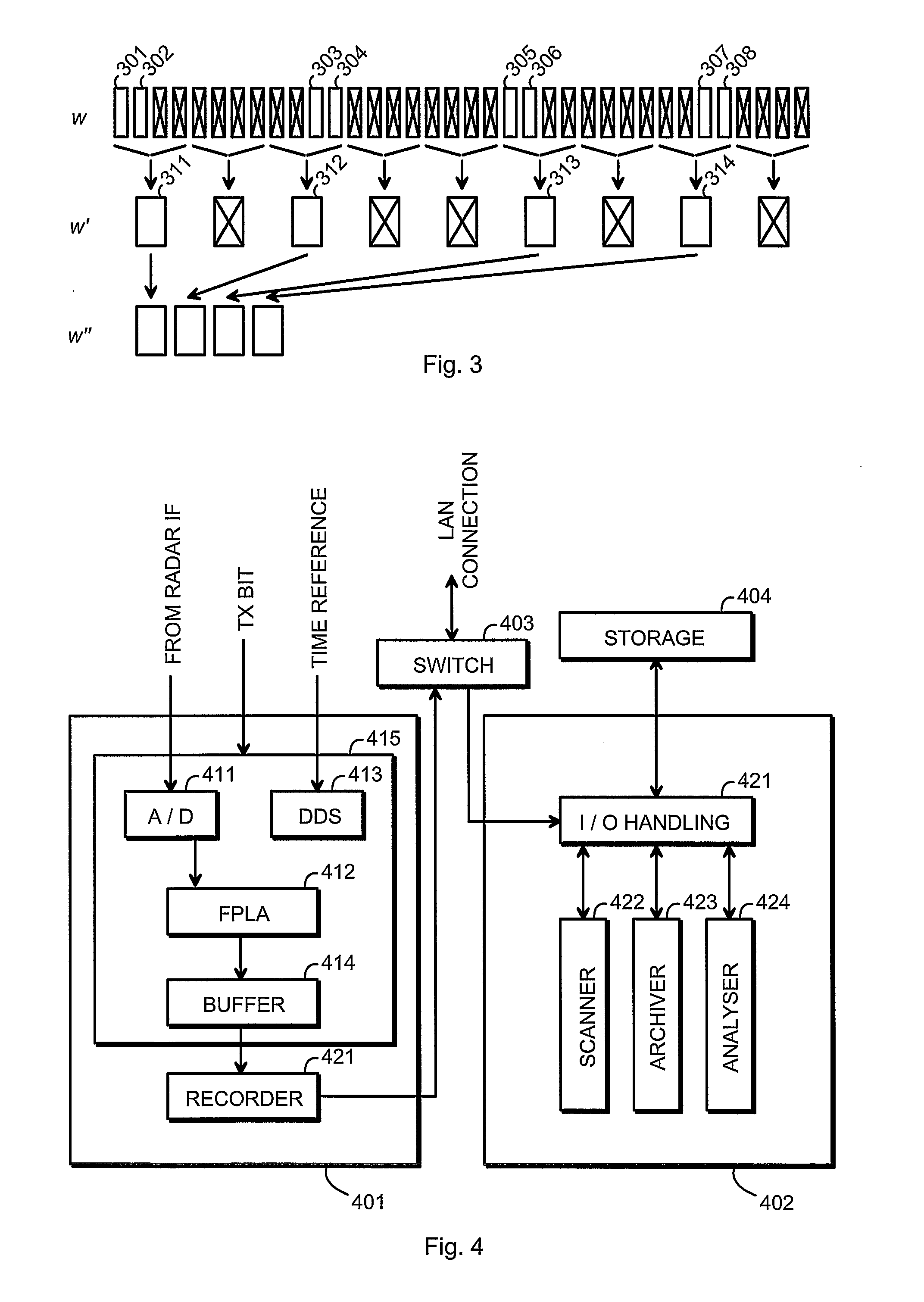
Moving objects are detected with a radar by collecting samples of a received signal over an integration period. The terms of a match function contain a product of a sample of said received signal and a delayed-in-time, Doppler-shifted replica of a transmission and depend on parameters that describe an object that caused a reflection of the transmission. The most probable values of the parameters are found by maximizing the match function through Fourier transforming a vector consisting of terms of the match function. Those of said products that contain a non-zero contribution of said delayed-in-time, Doppler-shifted replica of a transmission are actually computed while the others of said products are zero Only non-zero blocks of the products count as final terms to the vector to be Fourier transformed that have nonzero value while intermittent blocks that have zero value are left out. The most probable values of the parameters are those that result from Fourier transforming the vector consisting of the final terms.

Description

TECHNICAL FIELD[0001]The invention concerns the technical field of radar measurements. Especially the invention concerns the problem of how to process the raw data from digitally sampled radar measurements into meaningful information describing moving objects with a reasonable calculational effort. An object is said to be moving if it is in motion in relation to a radar beam that is used to detect it; the term “moving objects”thus encompasses also objects that are stationary in some inertial coordinate system but which are detected with a moving radar beam.BACKGROUND OF THE INVENTION[0002]Using a radar to obtain information about distant, moving targets is practical in a variety of cases, including but not being limited to military surveillance, commercial airborne and seaborne navigation as well as scientific research. In this patent application we use the detection of space debris as an example. However, the same principles also apply to other kinds of radar measurements.[0003]Spa...

Claims


Application Information

Patent Timeline
Patent Type & Authority Patents(United States)
IPC IPC(8): G01S13/72G01SG01S13/56
CPCG01S13/56
Inventor LEHTINEN, MARKKU SAKARI
Owner MELIORCOMP
Learn More