Inkjet head with conductive elastic member for electrical continuity between remote contacts in same

a technology of elastic member and conductive element, which is applied in the field ofinkjet head, can solve the problems of increased cost, chemical attack of piezoelectric device, and deterioration of piezoelectric device quality, and achieve the effect of ensuring electrical continuity

Active Publication Date: 2009-08-25
BROTHER KOGYO KK
View PDF12 Cites 6 Cited by
  • Summary
  • Abstract
  • Description
  • Claims
  • Application Information

AI Technical Summary

Benefits of technology

[0014]When compared with these two techniques with respect to the easiness to simplify the construction of related circuitry, the second technique is more advantageous than the first technique.
[0019]It is therefore an object of the present invention to provide an inkjet head including a nozzle unit and a printed circuit board, in which electrical continuity between these nozzle unit and printed circuit board can be achieved without requiring the process of mechanically fixedly connecting performed at each connection site.
[0029]a movement limiter limiting movement of the elastic member to thereby prevent the elastic member from being disengaged from the earth contact and the ground contact.
[0032]Further, in this inkjet head, the movement limiter limits the movement of the elastic member in a direction allowing the elastic member to be disengaged from the earth and ground contacts. Accordingly, the elastic member is prevented from being disengaged from the earth and ground contacts. As a result, the reliability of electrical continuity is assured between the earth and ground contacts.

Problems solved by technology

The failure to electrically hold these nozzle unit and support at the reference potential invites an event of charging ink within the nozzle unit.
If the ink is charged, then the piezoelectric device is chemically attacked (chemical erosion and corrosion occur in the piezoelectric device) due to the action of ionic compound in the ink, or the like.
This creates the fear that the piezoelectric device will be deteriorated in quality in a shortened time of use.
However, this constitutes one of factors causing an increase in cost.

Method used


Image

  • Inkjet head with conductive elastic member for electrical continuity between remote contacts in same
  • Inkjet head with conductive elastic member for electrical continuity between remote contacts in same
  • Inkjet head with conductive elastic member for electrical continuity between remote contacts in same

Examples


first embodiment

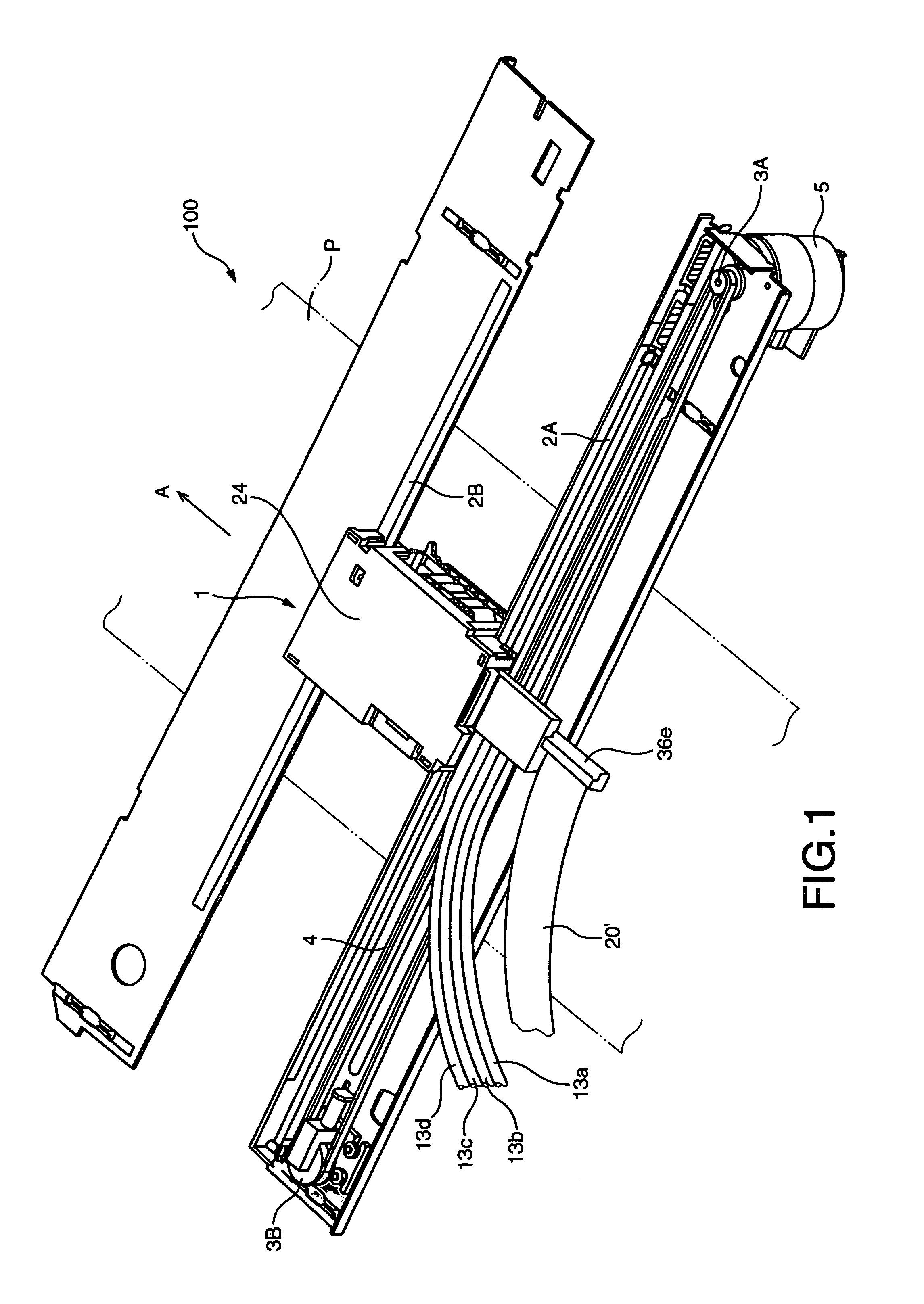
[0115]Referring now to FIG. 1, an inkjet head 1 according to the present invention is illustrated.

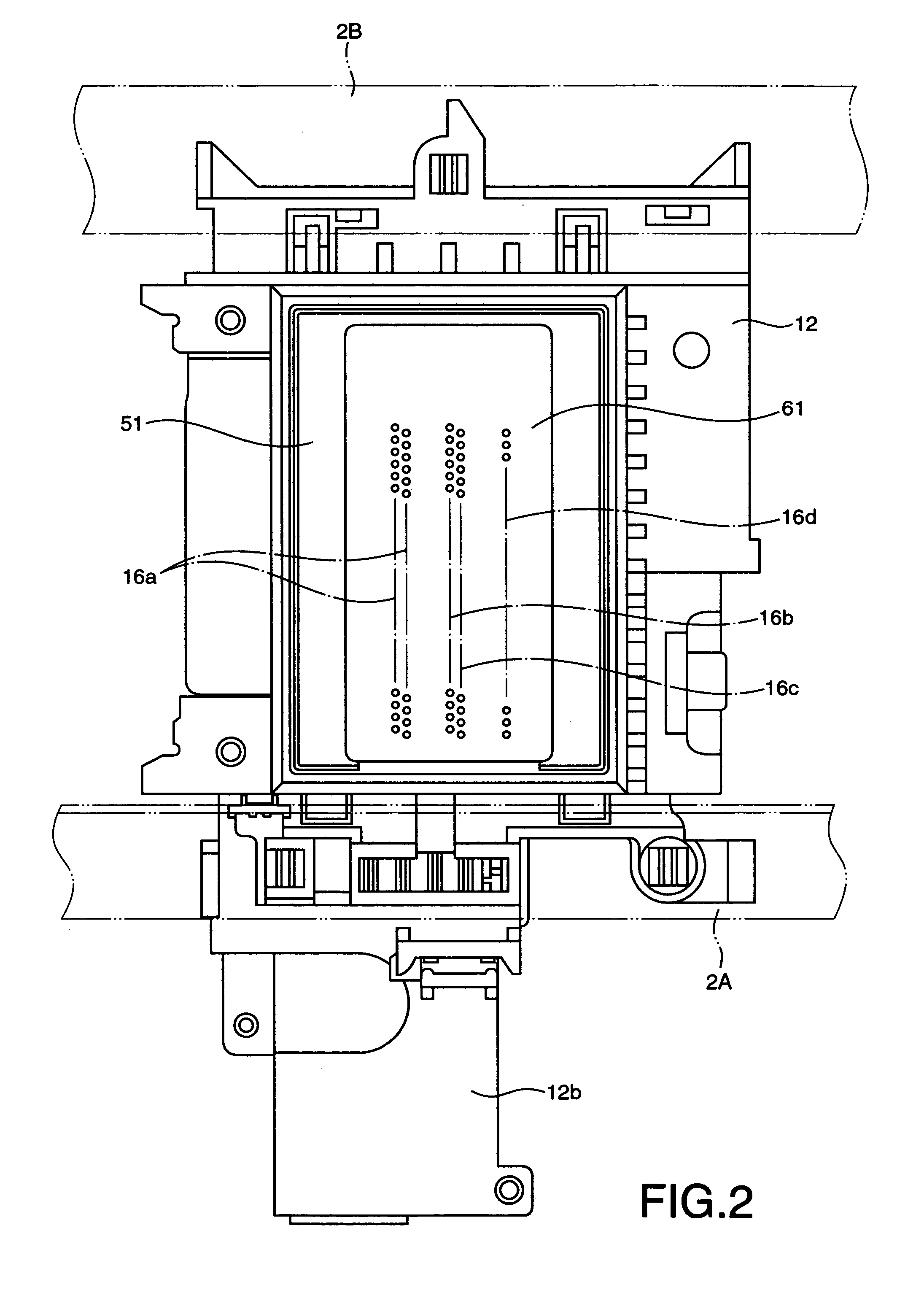
[0116]FIG. 1 is a perspective view illustrating relevant components of an inkjet printer 100 including the inkjet head 1, FIG. 2 is a bottom view illustrating the inkjet head 1, and FIG. 3 is an exploded perspective view illustrating the inkjet head 1.

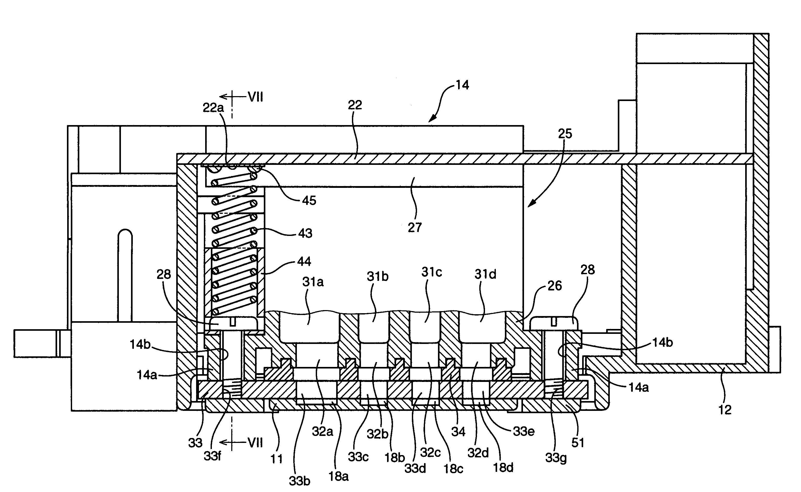
[0117]FIG. 4 is a top plan view partly in section of the inkjet head 1, and FIG. 5 is a cross sectional view taken on line V-V in FIG. 4.

[0118]As illustrated in FIG. 1, the inkjet printer 100 includes the inkjet head 1. As illustrated in FIG. 3, the inkjet head 1 includes a thin-plate-shaped nozzle unit 11, and a head holder 12 made of a synthetic resin on which the nozzle unit 11 is mounted. The nozzle unit 11 including a plurality of nozzles is used for ejecting ink droplets through the nozzles in an inkjet manner.

[0119]As illustrated in FIG. 1, in the inkjet printer 100, ink is supplied from an ink tank (not shown) via ink supply tubes ...

second embodiment

[0183]Next, with reference to FIG. 9, an ink jet head 1 constructed according to the present invention will be described.

[0184]In view of the fact that the present embodiment is substantially common in basic construction to the first embodiment except elements relating to a recessed portion, the common elements of the present embodiment to those of the first embodiment will be referenced the same reference numerals as those in the description and illustration of the first embodiment, without a redundant description and illustration, while the different elements of the present embodiment from those of the first embodiment will be described in more detail.

[0185]In the present embodiment, as with the first embodiment, the coil spring 43 is inserted at its bottom end into the cylindrical member 44, while the coil spring 43 is in contact at its top end with the ground contact 22a of the printed circuit board 22, with the movement of the top end of the coil spring 43 being suppressed by a...

third embodiment

[0188]Next, with reference to FIG. 10, an ink jet head 1 constructed according to the present invention will be described.

[0189]In view of the fact that the present embodiment is substantially common in basic construction to the first embodiment except elements relating to the scheme of supporting the coil spring 43, the common elements of the present embodiment to those of the first embodiment will be referenced the same reference numerals as those in the description and illustration of the first embodiment, without a redundant description and illustration, while the different elements of the present embodiment from those of the first embodiment will be described in more detail.

[0190]In the first embodiment, the top end of the coil spring 43 is supported by the recessed portion 45 which is fixedly formed in the ground contact 22a of the printed circuit board 22. In contrast, in the present embodiment, the top end of the coil spring 43 is supported by an electrically insulative cyli...


PUM


Abstract

An inkjet head for ejecting ink droplets is disclosed which includes: a nozzle unit having metal thin plates and a piezoelectric device, adapted to eject the ink droplets; a printed circuit board supplying to the piezoelectric device a drive signal for causing the nozzle unit to eject the ink droplets; a support supporting the nozzle unit and the printed circuit board in opposing relationship to each other; an earth contact disposed on the nozzle unit; a ground contact disposed on the printed circuit board, held at a reference potential; an electrically conductive elastic member disposed between the earth and ground contacts, such that portions of the elastic member are in electrical contact with the earth and ground contacts, respectively; and a movement limiter limiting movement of the elastic member to thereby prevent the elastic member from being disengaged from the earth and ground contacts.

Description

[0001]This application is based on Japanese Patent Application No. 2004-279396 filed Sep. 27, 2004, the content of which is incorporated hereinto by reference.CROSS-REFERENCE TO RELATED APPLICATIONS[0002]Not Applicable.BACKGROUND OF THE INVENTION[0003]1. Field of the Invention[0004]The invention relates to an inkjet head for use in an inkjet printer, and more particularly to techniques of achieving electrical continuity between remote contacts in the inkjet head.[0005]2. Description of the Related Art[0006]There are known inkjet heads for use in inkjet printers, which each incorporate a nozzle unit including a plurality of metal thin plates and a piezoelectric device. During a print operation of such a kind of inkjet head, drive signals are delivered to the piezoelectric device for ejecting ink droplets through nozzles contained in the nozzle unit, resulting in the formation of the desired image on a print medium.[0007]More specifically, such a type of inkjet head is structured such...

Claims


Application Information

Patent Timeline
Patent Type & Authority Patents(United States)
IPC IPC(8): B41J2/16B41J2/05
CPCB41J2/14201B41J2002/14491
Inventor ITO, ATSUSHIKATO, YASUHIROOKAZAKI, NAOYATAKATA, MASAYUKI
Owner BROTHER KOGYO KK
Why Eureka
Try Eureka