Enclosures with redundant fans in doors with interlocks

a technology of interlocking doors and enclosures, applied in the field of enclosures, can solve the problems of device failure, device speed and power consumption increase, and disruption of airflow over electronic devices, so as to prevent electronic device failure from overheating and sufficient airflow

Active Publication Date: 2009-08-25
HEWLETT-PACKARD ENTERPRISE DEV LP +1
View PDF8 Cites 9 Cited by
  • Summary
  • Abstract
  • Description
  • Claims
  • Application Information

AI Technical Summary

Benefits of technology

[0003]An enclosure including front and back doors is configured with fans for air cooling enclosed electronic devices in both doors. The fans in each door are sufficient, by themselves, to provide sufficient airflow to cool the electronic devices. The two doors include switches and magnetic interlocks configured such that when one door is opened, the magnetic interlock on the other door is activated preventing both doors from being opened at the same time. This ensures that at least one door is always closed while the system is powered up, and since the fans in each door provide sufficient cooling for the enclosure, the enclosure is always sufficiently cooled to prevent electronic device failure from overheating.

Problems solved by technology

As electronic devices increase in speed and power consumption, cooling these devices becomes critical to their proper operation.
Particularly when placed inside enclosures, which may modify the natural airflow around the device, proper cooling device operation is critical.
However, it is sometimes necessary to open either the front door or the back door of the enclosure while the electronic devices within the rack are operating.
In this case, if the fans are mounted on the door that is opened, the airflow over the electronic devices may be disrupted while the door is open, and the devices may overheat to the point of failure.
However, if both doors are opened at the same time, the fans in the front and back doors are no longer providing airflow, and the electronic devices may overheat to the point of failure.

Method used


Image

  • Enclosures with redundant fans in doors with interlocks
  • Enclosures with redundant fans in doors with interlocks
  • Enclosures with redundant fans in doors with interlocks

Examples


Embodiment Construction

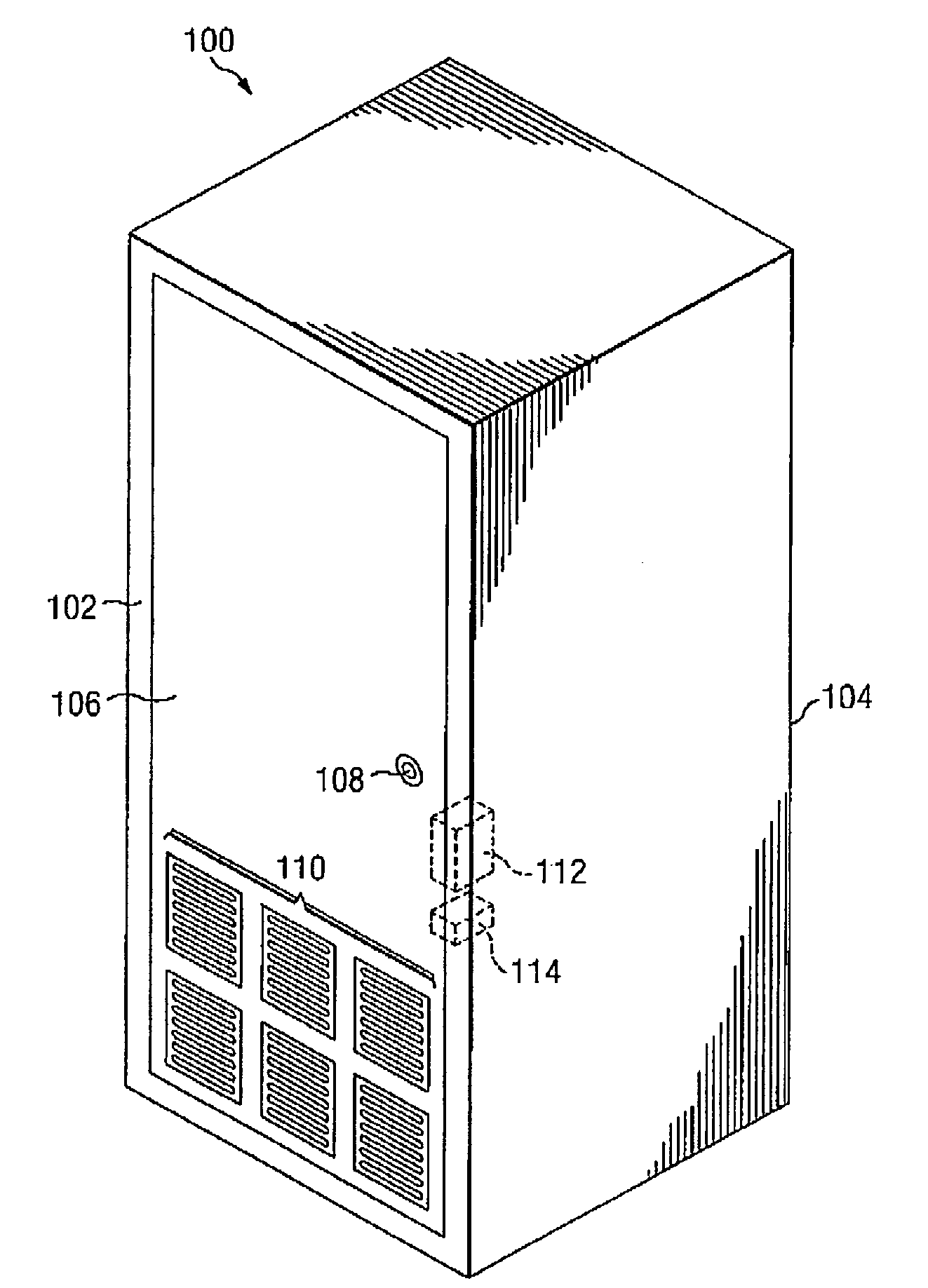
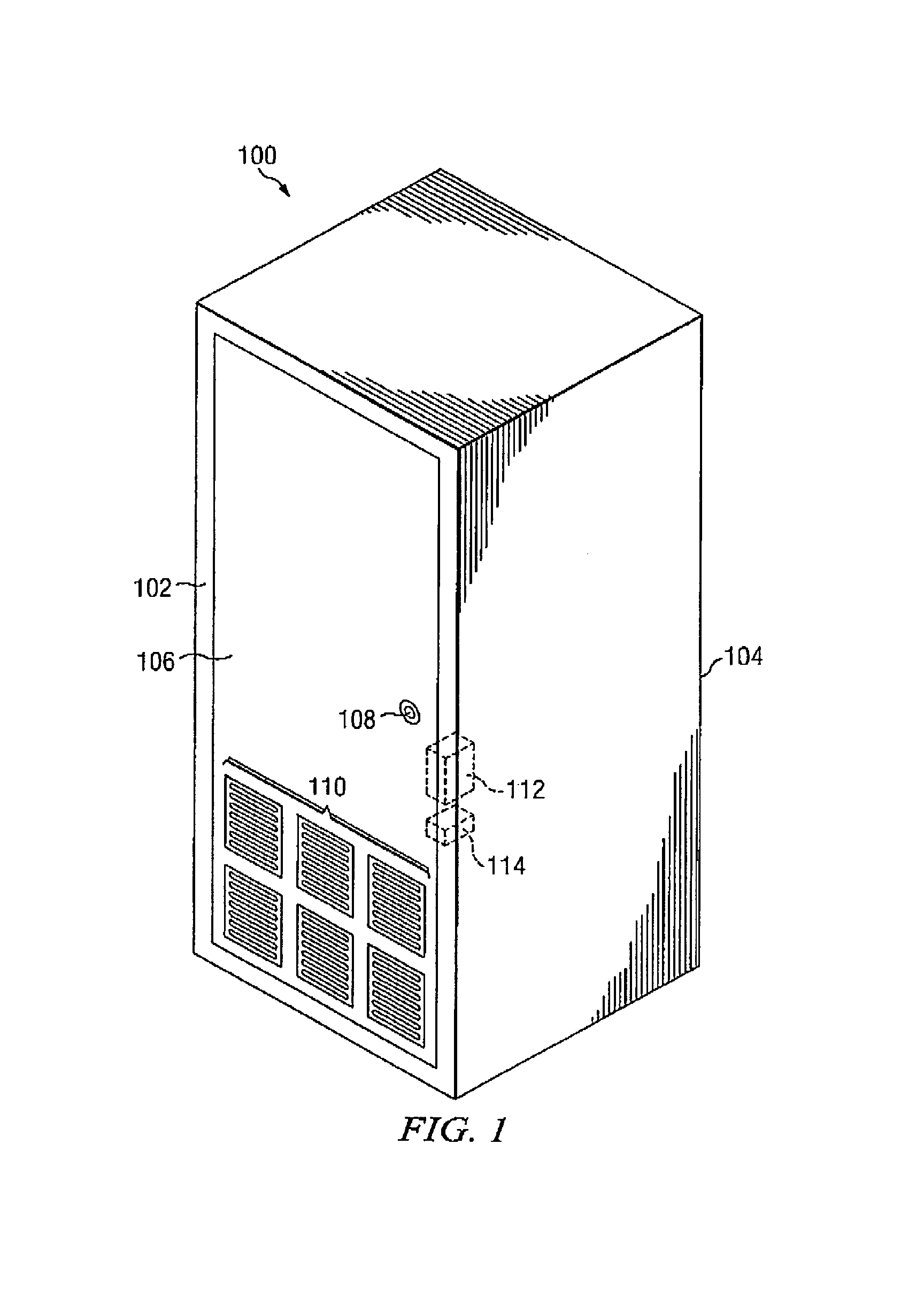
[0010]FIG. 1 is a view of an enclosure including a front door according to the present invention. The example embodiment of the present invention shown in FIG. 1 is an enclosure 100 including a front 102 and a back 104. The front 102 of the enclosure 100 includes a front door 106. The front door 106 includes a lock 108, at least one fan 110, a switch 114 configured to close when the front door 106 is opened, and a latch 112. This latch 112 is configured to activate and prevent opening of the front door 106 when the power to the enclosure 100 is on, and the back door 200 is open. Those of skill in the art will recognize that there are many different ways of implementing the latch 112 within the scope of the present invention. For example, any of the variety of magnetic latches may be used, mechanical latches activated by a solenoid, or simple solenoid latches may be used within the scope of the present invention.

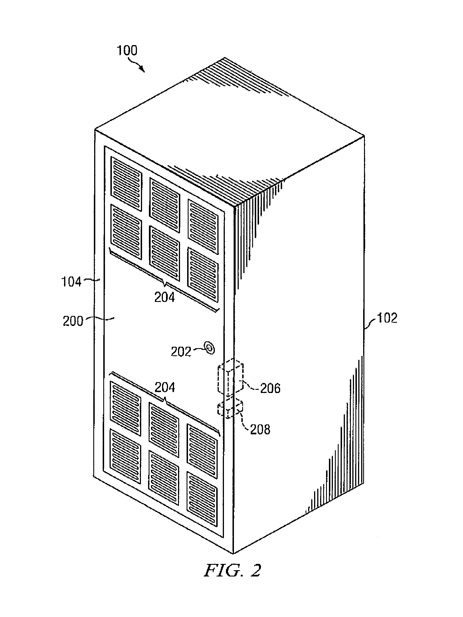
[0011]FIG. 2 is a view of an enclosure including a back door according t...


PUM


Abstract

An equipment rack including front and back doors is configured with fans for air cooling enclosed electronic devices in both doors. The fans in each door are sufficient, by themselves, to provide sufficient airflow to cool the electronic devices. The two doors include switches and magnetic interlocks configured such that when one door is opened, the magnetic interlock on the other door is activated preventing both doors from being opened at the same time. This ensures that at least one door is always closed while the system is powered up, and since the fans in each door provide sufficient cooling for the equipment rack, the rack is always sufficiently cooled to prevent electronic device failure from overheating.

Description

FIELD OF THE INVENTION[0001]The present invention relates generally to the field of enclosures, and more particularly to the field of enclosures including cooling fans and front and back doors.BACKGROUND OF THE INVENTION[0002]As electronic devices increase in speed and power consumption, cooling these devices becomes critical to their proper operation. Particularly when placed inside enclosures, which may modify the natural airflow around the device, proper cooling device operation is critical. Many enclosures include fans on either a front door or a back door to force air through the enclosure (since the sides are often solid) cooling the enclosed electronic devices. However, it is sometimes necessary to open either the front door or the back door of the enclosure while the electronic devices within the rack are operating. In this case, if the fans are mounted on the door that is opened, the airflow over the electronic devices may be disrupted while the door is open, and the device...

Claims


Application Information

Patent Timeline
Patent Type & Authority Patents(United States)
IPC IPC(8): H05K5/00G06F1/20H05K7/20
CPCH05K5/0208
Inventor BELADY, CHRISTIAN L.PETERSON, ERIC C.
Owner HEWLETT-PACKARD ENTERPRISE DEV LP
Why Eureka
Try Eureka