Unit ventilator having a splitter plate and a pivoting damper blade assembly

a unit ventilator and damper blade technology, which is applied in the field of unit ventilators, can solve the problems of affecting the overall cost and reliability of the unit, the damper blades of the unit ventilator are not very well sealed, and the damper blades are simple and flat,

Active Publication Date: 2009-08-25
TRANE INT INC
View PDF17 Cites 55 Cited by
  • Summary
  • Abstract
  • Description
  • Claims
  • Application Information

AI Technical Summary

Benefits of technology

[0010]It is an object of the invention to provide a unit ventilator with a direct-driven damper blade unit that helps control the proportions of outside air and return air being drawn into the ventilator.
[0011]Another object of some embodiments is provide a relatively long, narrow damper blade unit with an outside air damper blade, a return air damper blade, and a pair of gussets that combine to create a concavity in the damper blade unit, thereby creating a box-like structure that is more rigid than a simple planar blade.
[0015]Another object of some embodiments is to stiffen a damper blade with a gusset and a rib that lie perpendicular to each other.
[0016]Another object of some embodiments is to cover an outside air damper with a layer of insulation to help prevent frost and condensation from collecting on the damper.

Problems solved by technology

The linkages and gears for driving and coordinating the movement of the dampers can adversely affect the unit's overall cost and reliability.
These dampers, however, are quite planar, and although that may be fine for their particular application, simple flat dampers do not work well for unit ventilators, which tend to be rather long and narrow.
Long, flat damper blades tend to twist and bend, thus they do not seal very well.
Moreover, since unit ventilators are usually installed in the same room as the occupants, the amount of space consumed by the ventilator is a major concern.
If a unit ventilator's blower, heat exchanger, damper system and filter are simply stacked one atop the other, the resulting unit can be unreasonably large and bulky.

Method used


Image

  • Unit ventilator having a splitter plate and a pivoting damper blade assembly
  • Unit ventilator having a splitter plate and a pivoting damper blade assembly
  • Unit ventilator having a splitter plate and a pivoting damper blade assembly

Examples


Embodiment Construction

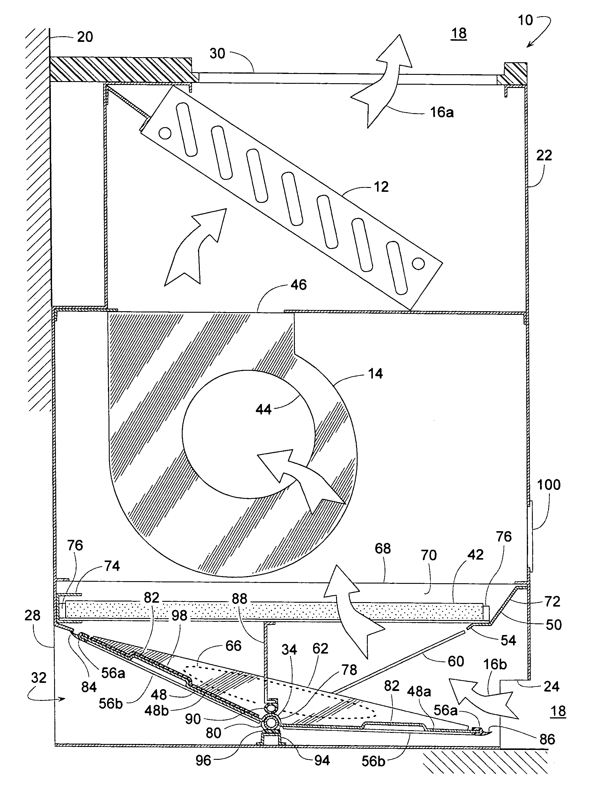
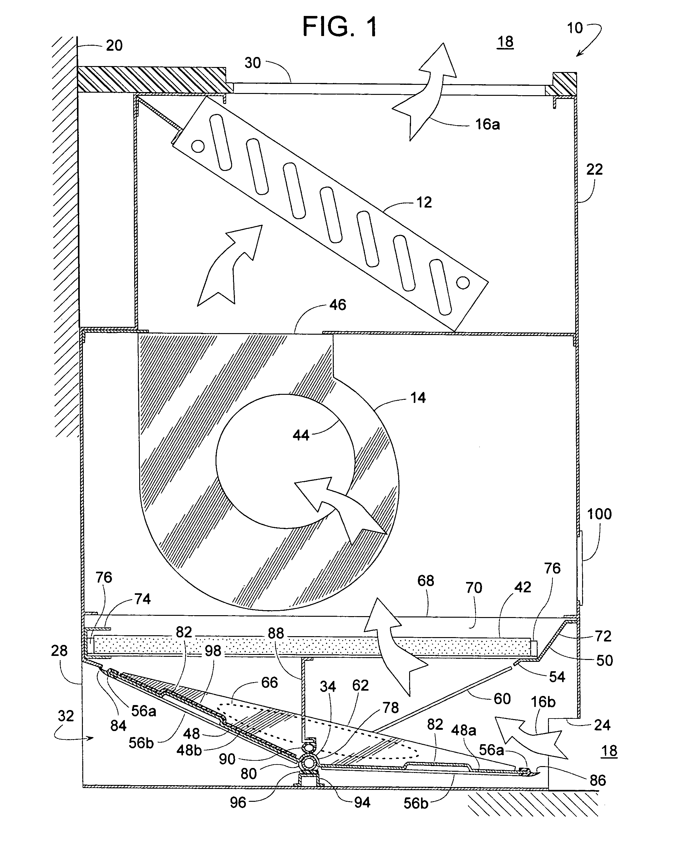
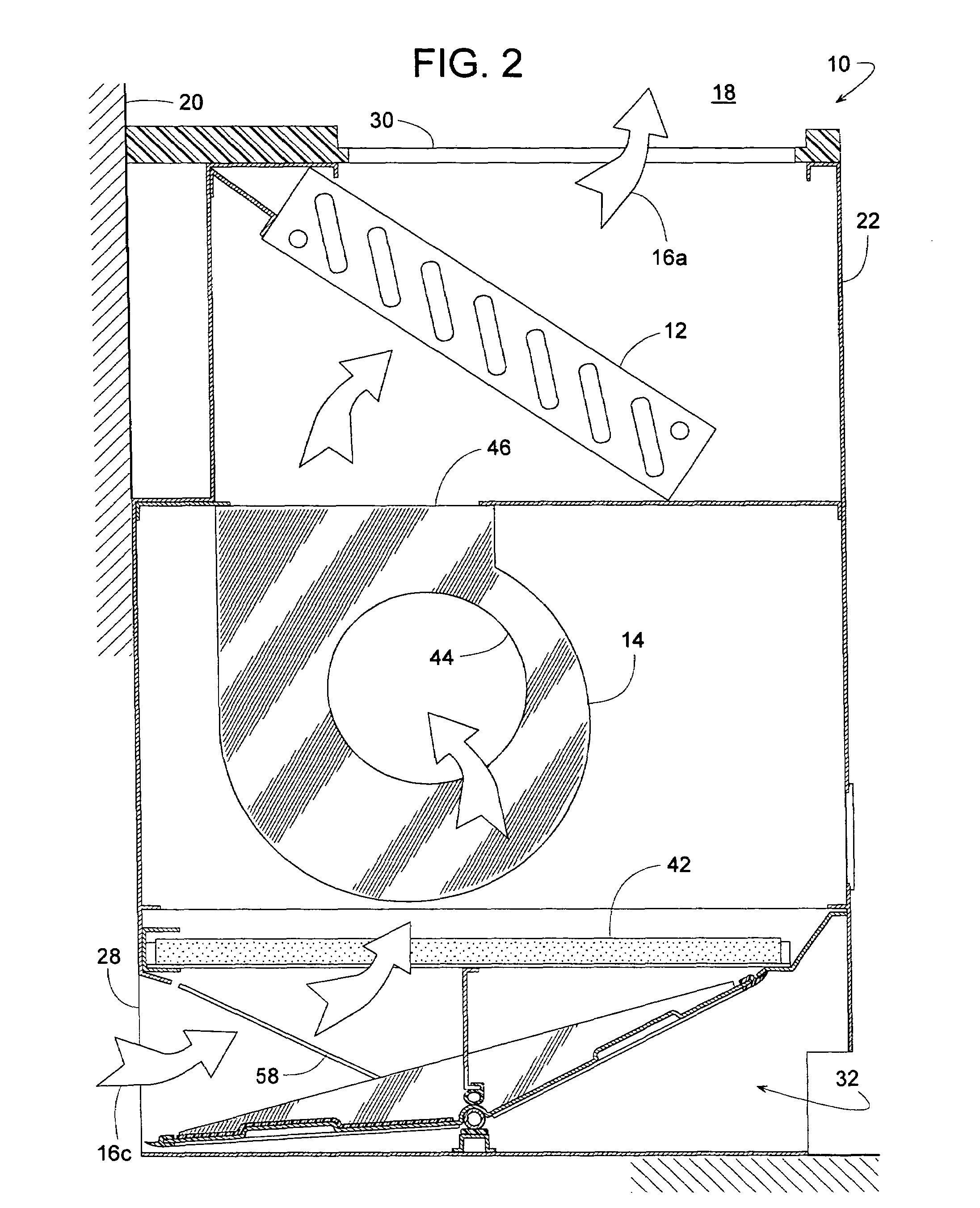
[0024]Referring to FIGS. 1-3, a unit ventilator 10 includes a heat exchanger 12 (e.g., evaporator, condenser, water chilled coil, water heated coil, electric heater, etc.) and a blower 14 for discharging a current of supply air 16a into a comfort zone 18, such as a room or other area within a building 20. Blower 14 and heat exchanger 12 are contained within an enclosure 22 that defines a return air inlet 24 for receiving used return air 16b from comfort zone 18, an outside air inlet 28 for receiving fresh outside air 16c, and a supply air outlet 30 for releasing supply air 16a into comfort zone 18.

[0025]Referring further to FIG. 4, ventilator 10 also includes a damper assembly 32 with a damper shaft 34 that can pivot about an axis 36 (longitudinal centerline of shaft 34) to determine the supply air's mixture of outside air 16c and return air 16b. A drive unit 38, such as an electric motor or some other rotational actuator, includes a drive shaft 40 directly coupled to damper shaft 3...


PUM


Abstract

An HVAC unit ventilator, particularly suited for schools and hotels, includes a single damper blade driven directly by a motor to control a supply air's mixture of return air and outside air. The damper blade is selectively pivotal to a full outside air position, a full return air position, and various intermediate mixed-air positions. The damper blade has flexible edge and end seals that create little if any frictional drag as the damper blade pivots to the intermediate positions, yet the seals provide a positive, tight seal when the damper stops at either the full outside air position or the full return air position. The unit ventilator includes a filter frame that not only supports an air filter but also provides the damper blade with sealing surfaces and structural support. For rigidity, the damper blade has somewhat of a box-like structure that is bi-directionally reinforced by ribs and triangular gussets.

Description

BACKGROUND OF THE INVENTION[0001]1. Field of the Invention[0002]The subject invention generally pertains to HVAC unit ventilators such those often used in classrooms and hotels. The invention more specifically pertains to a damper assembly that apportions the amount of outside air and return air to such a ventilator.[0003]2. Description of Related Art[0004]HVAC unit ventilators typically include a blower, heat exchanger, and a damper assembly for independently controlling the heating or cooling of separate rooms of a multi-room building such as a school or hotel. The building may have numerous unit ventilators whose individual heat exchangers receive their heat or cooling energy from a commonly shared source, such as a central boiler or chiller. When a unit ventilator includes a DX coil for cooling, the coil is usually associated with its own condenser rather than a central one.[0005]Unit ventilators are typically mounted against an outer wall of the building so that they can draw i...

Claims


Application Information

Patent Timeline
Patent Type & Authority Patents(United States)
IPC IPC(8): F24F13/12F24F1/0035F24F1/0073
CPCF24F1/0007F24F13/14F24F2001/0051F24F2001/0044F24F1/0053F24F1/0035F24F1/0073
Inventor AHMED, SYED S.SAWYER, KEVIN W.HERZOG, BRYAN M.HALL, KIM L.BEASON, KIRK W.
Owner TRANE INT INC
Why Eureka
Try Eureka