System for actuating a laparoscopic surgical instrument

a technology of laparoscopic surgery and tip actuation, which is applied in the field of laparoscopic surgical instruments, can solve the problems of increased tension, increased user's discomfort, and decreased comfort of users, and achieves the effect of increasing tension and reducing discomfor

Active Publication Date: 2009-08-25
APPL MEDICAL RESOURCES CORP
View PDF18 Cites 89 Cited by
  • Summary
  • Abstract
  • Description
  • Claims
  • Application Information

AI Technical Summary

Benefits of technology

[0008]The invention is directed to a pin and slot design where the driving slots are moved from the blades or tips to the actuation rod in one aspect of the invention. As a result, the back end of each blade or tip can be dramatically reduced in area so that during full deflection, very little or no part of the blade or tip extends beyond the outside diameter of the outer tube or shaft. This ensures that nothing catches on the blades or tips during grasper use and the shrink tubing found on the scissors would not be deformed. This can be done because the area for the slots is not needed. Moreover, the usable area for the drive slots on the blade or tip of the actuation rod is maximized to the overall diameter of the outer tube or shaft which provides additional leverage to the blades or tips. In addition, the depth of the slot can be varied such that increased tension can be placed on the blades or tips during actuation.

Problems solved by technology

When used on a grasper and the tips are in their open position, the back end of the tips extend out beyond the outside diameter of the grasper shaft and look like “wings.” This may be a problem for the user and, in particular, the patient as they can catch or interfere on tissue or other devices during use.
However, when the blades or tips are open, the wings can stretch and deform the shrink tubing.
This can be problematic in that when the scissors is withdrawn from the trocar, the deformed tubing may not relax and it may catch on the end of the cannula, thereby pulling the trocar out of the patient.

Method used


Image

  • System for actuating a laparoscopic surgical instrument
  • System for actuating a laparoscopic surgical instrument
  • System for actuating a laparoscopic surgical instrument

Examples


Embodiment Construction

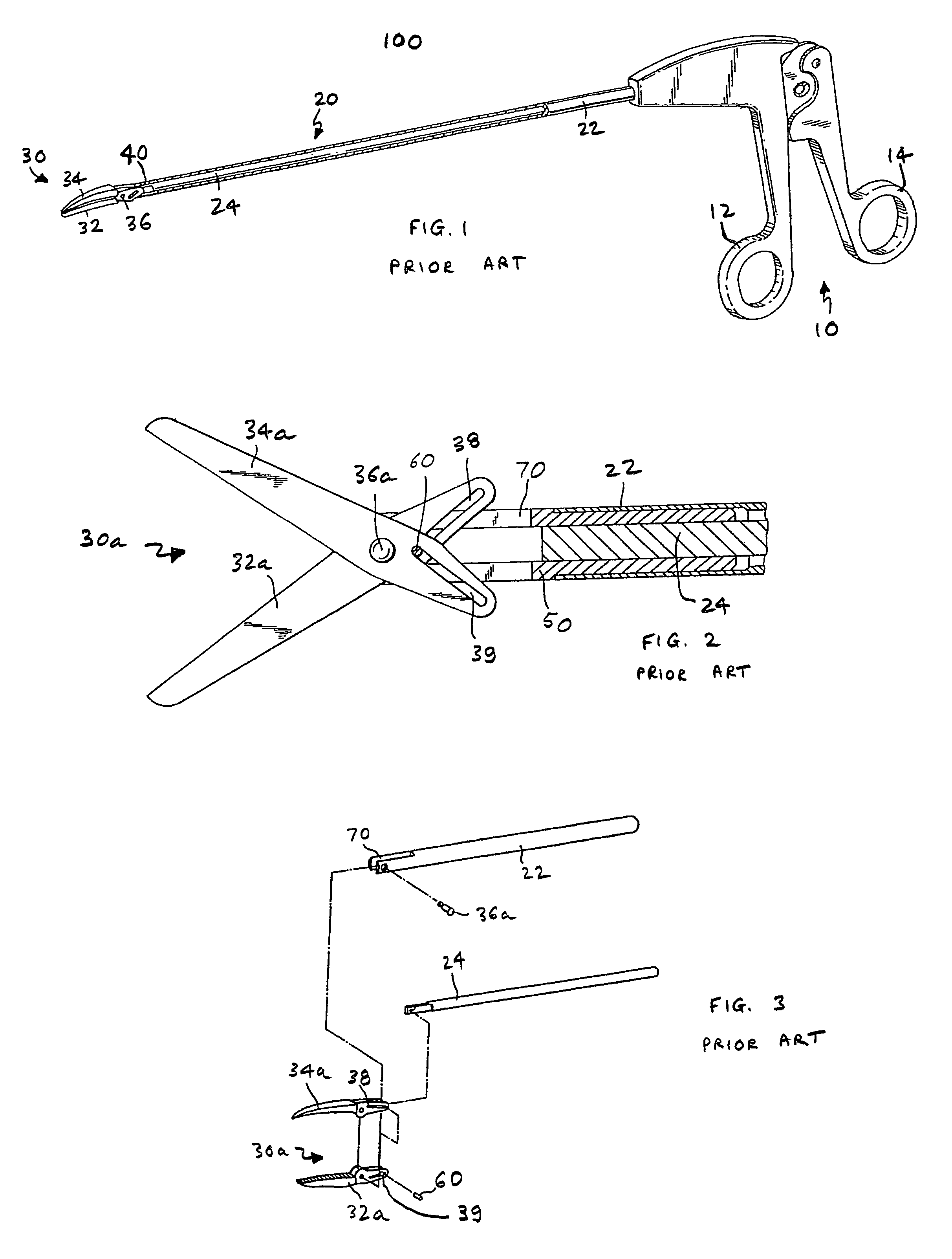
[0029]Referring to FIG. 1, there is shown a perspective view of a laparoscopic surgical instrument 100 of the prior art as shown in U.S. Pat. No. 5,626,609, which is incorporated herein by reference. The surgical instrument 100 typically comprises a handle assembly 10 having a fixed handle 12 and a pivoting handle 14. Extending from the handle assembly 10 is a shaft assembly 20 comprising an outer tube 22 and an inner actuation rod 24. The actuation rod 24 slides in the outer tube 20 in a coaxial relationship. The outer tube 22 may be secured to the fixed handle 12, while the actuation rod 24 may be secured to the pivoting handle 14. Attached at a distal end of the shaft assembly 20 is a tool mechanism 30, which comprises of a lower jaw 32 and an upper jaw 34. The tool mechanism 30 is connected to the shaft assembly 20 at pivot point 36 through linkage mechanism 40. During use, as the actuation rod 24 slides within the outer tube 22, the linkage mechanism 40 is actuated to pivot jaw...


PUM


Abstract

The invention is directed to a pin and slot design where the driving slots are moved from the tips to the actuation rod in one aspect of the invention. As a result, the back end of each blade or tip can be dramatically reduced in area so that during full deflection, very little or no part of the blade or tip extends beyond the outside diameter of the shaft. This ensures that nothing catches on the blades or tips during grasper use and the shrink tubing found on the scissors would not be deformed. This can be done because the area for the slots is not needed. Moreover, the usable area for the drive slots on the blade or tip of the actuation rod is maximized to the overall diameter of the outer tube or shaft which provides additional leverage to the blades or tips. In addition, the depth of each slot can be varied such that during actuation, increased tension can be put on the blades or tips throughout the cut. More specifically, the surgical instrument of the invention comprises an elongate tube extending along an axis including an actuation rod coaxially slidable within the elongate tube, a first tip including a first pin formed on a proximal end surface of the first tip, and a second tip including a second pin formed on a proximal end surface of the second tip, the second tip pivotally connected to the first tip at a common pivot pin operably connected to the elongate tube to open and close the tips in response to movement of the actuation rod. The actuation rod has a slot to accept the pins of the first and second tips, the slot has camming surfaces for the pins to slide within the slot, and the proximal ends of the tips extend minimally outside the diameter of the elongate tube during actuation of the tips.

Description

[0001]This is a non-provisional application claiming the priority of provisional application Ser. No. 60 / 548,747, filed on Feb. 27, 2004, entitled “System and Method of Actuating a Laparoscopic Surgical Instrument,” which is fully incorporated herein by reference.BACKGROUND OF THE INVENTION[0002]1. Field of the Invention[0003]This invention generally relates to laparoscopic surgical instruments and, in particular, to a system and method for actuating the tips of a laparoscopic surgical instrument.[0004]2. Description of Prior Art[0005]Laparoscopic surgical instruments or devices that use actuating blades or tips are typically activated by some mechanical means. In most cases, the surgical instruments or devices use an actuation rod to translate motion from a handle at one end to a tip at the opposite end of the device. Common to laparoscopic scissors and graspers is an actuation rod that includes a pin that works in conjunction with a slot in the tips. Moving the actuation rod cams ...

Claims


Application Information

Patent Timeline
Patent Type & Authority Patents(United States)
IPC IPC(8): A61B17/29A61B17/3201A61B17/04A61B17/28A61B17/32
CPCA61B17/1608A61B17/29A61B17/32A61B17/3201A61B17/320016A61B2017/2936A61B2017/2932A61B2017/2934
Inventor JOHNSON, GARY M.AHLBERG, RUSSELL E.OKIHISA, DAVIDBAK-BOYCHUK, GREGORY I.
Owner APPL MEDICAL RESOURCES CORP
Why Eureka
Try Eureka