
System for and method of communicating control information between entities interconnected by backplane connections

a backplane connection and control information technology, applied in the field of networked systems involving entities interconnected by backplane connections, can solve the problems of complex communication, difficult to meet the needs of users, and difficult to communicate, and achieve the effect of improving the service life and improving the service li

Active Publication Date: 2009-08-25
EXTREME NETWORKS INC
View PDF9 Cites 39 Cited by
  • Summary
  • Abstract
  • Description
  • Claims
  • Application Information

AI Technical Summary

Benefits of technology

[0008]In a first aspect of this disclosure, a system for communicating control information over one or more backplane connections between two or more entities is described. In this system, first logic stores the control information within a layer of a packet above the physical layer. In one embodiment, the control infor

Problems solved by technology

Such communications pose significant challenges given that backplane connections are often subject to tight bandwidth constraints or limitations.
Various approaches have emerged in response to these challenges, none of which are entirely satisfactory.
A limitation of this approach is that it can only be used if sufficiently tight ownership and control is maintained over the physical layer to ensure that the changes to the packet pre-amble will not disrupt or interfere with physical transmission of the packet.
This condition, however, is generally not possible to meet.
Many applications, however, impose cost and space constraints which prohibit the overhead of additional signal lines.
Thus, this approach also has limited applicability.
So, this approach only allows for in-band transmission of a very limited amount of proprietary control information, i.e., up to 4 bytes.
This is insufficient for all but the most limited applications.

Method used


Image

  • System for and method of communicating control information between entities interconnected by backplane connections
  • System for and method of communicating control information between entities interconnected by backplane connections
  • System for and method of communicating control information between entities interconnected by backplane connections

Examples


example environment

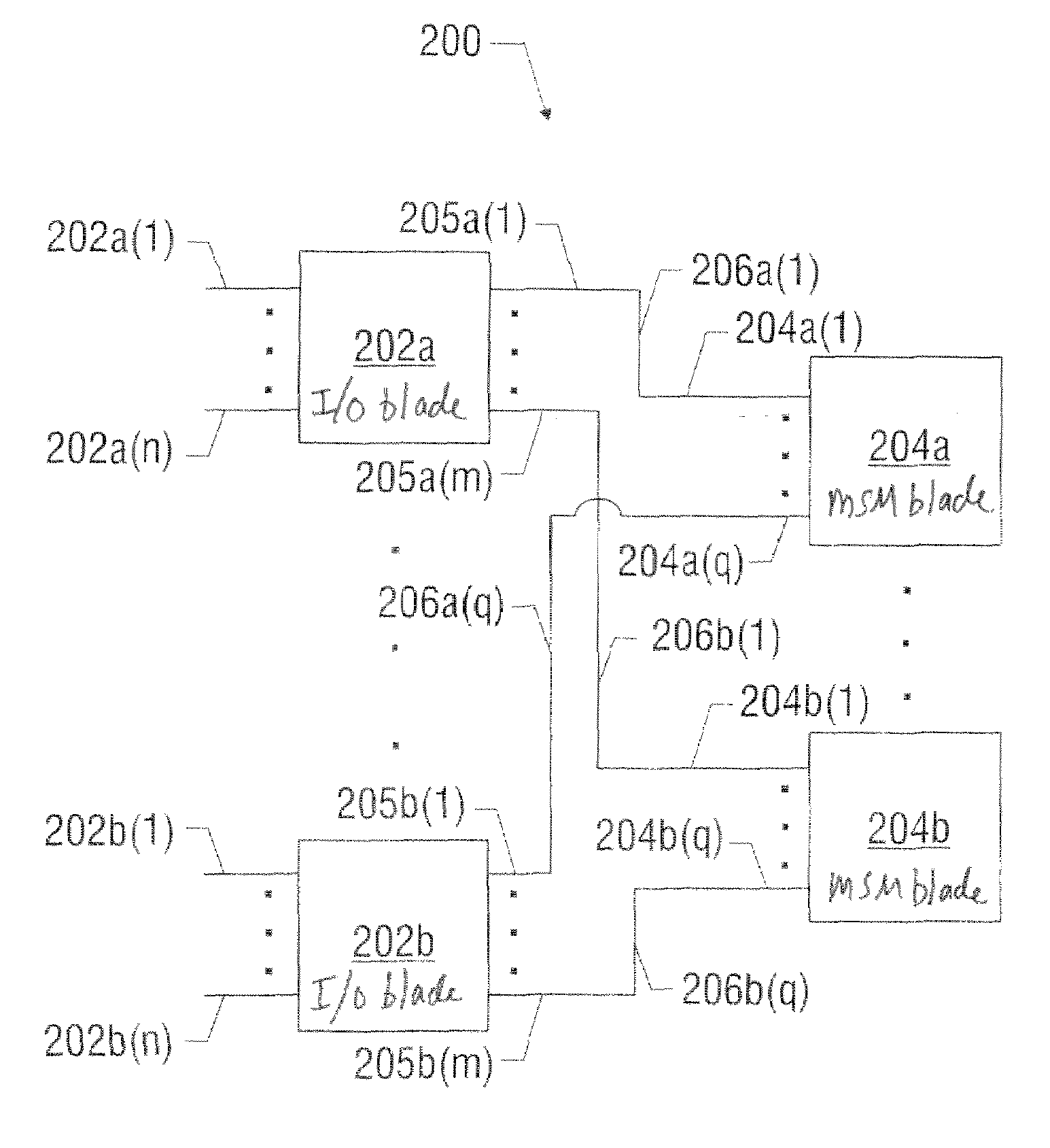
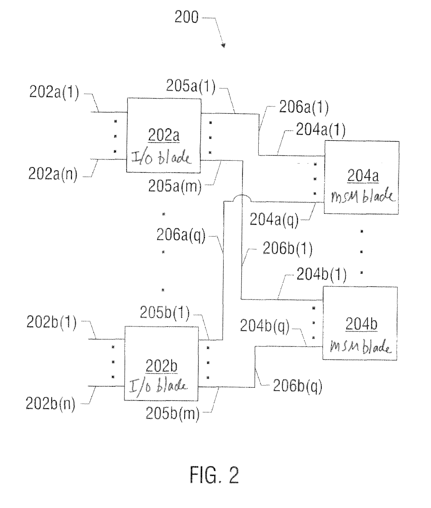
[0046]FIG. 2 illustrates an example environment in which the invention may be employed. The following description of this example environment is being provided to provide context for the invention and promote understanding of the invention. However, many other examples are possible so nothing in FIG. 2 or the description thereof should be taken as limiting.

[0047]FIG. 2 illustrates a switch 200 comprising one or more I / O blades 202a, 202b interconnected with one or more management / switching (MSM) blades 204a, 204b. Each I / O blade is configured with n network side ingress or egress ports, where n is an integer of 1 or more, and m backplane side ingress or egress ports, where m is an integer of 1 or more. The n network side ingress or egress ports for I / O blade 202a are identified with numerals 202a(1) to 202a(n), and those for I / O blade 202b with numerals 202b(1) to 202b(n). The m backplane side ingress or egress ports for I / O blade 204a are identified with numerals 205a(1) to 205a(m)...


PUM


Abstract

A system of and method for communicating control information between two or more entities over one or more backplane connections is described. The control information is stored in a layer of the packet above the physical layer and the packet is then communicated over the one or more backplane connections. A system of and method for performing load balancing over one or more backplane connections is also described. Control information for a packet is mapped into one or more identifiers of one or more of a plurality of backplane connections, and the packet is then communicated over the one or more identified backplane connections. A system of and method for extending the number of ports of a switch is further described. A first switch coupled to a second switch and having a greater number of ports than the second switch is provided. An identifier of a port of the first switch is stored in a layer of the packet above the physical layer. The packet is then communicated between the first and second switches.

Description

1. FIELD OF THE INVENTION[0001]This invention relates to the field of networked systems involving entities interconnected by backplane connections, and, more specifically, to communicating packet control information through backplane communications which are subject to bandwidth limitations.2. RELATED ART[0002]Many network environments call for various entities, including but not limited to processors, switches, routers, gateways, asynchronous integrated circuit chips (ASICs), media access controllers (MAC), switching fabric, or the like, to be interconnected by backplane connections. A backplane connection is often found between two or more entities situated within a single chassis, but may also occur between two or more remotely situated entities not confined to a single chassis.[0003]It is often necessary to communicate packet control information between two or more entities interconnected by a backplane connection for various tasks or functions such as packet classification, qua...

Claims


Application Information

Patent Timeline
IPC IPC(8): H04L12/28
CPCH04L49/253H04L49/352H04L49/552H04L49/40
Inventor SWENSON, ERIK R.HADDOCK, STEPHEN R.
Owner EXTREME NETWORKS INC
Features
  • Generate Ideas
  • Intellectual Property
  • Life Sciences
  • Materials
  • Tech Scout
  • Unparalleled Data Quality
  • Higher Quality Content
  • 60% Fewer Hallucinations
Learn More