
Display device

a technology of display device and display screen, which is applied in the direction of identification means, lighting and heating apparatus, instruments, etc., can solve the problem that the display device can extend a limitation, and achieve the effect of low manufacturing cos

Inactive Publication Date: 2009-09-01
CALSONIC KANSEI CORP
View PDF2 Cites 12 Cited by
  • Summary
  • Abstract
  • Description
  • Claims
  • Application Information

AI Technical Summary

Benefits of technology

The present invention provides a display device that can selectively display different display contents using ultraviolet light and color light. The device includes a filter that can selectively hit the ultraviolet light and produce visible light when the color light is emitted. The device can display the overlapping parts of different display contents in different colors, including a color different from the filter. The device can also have a smoke area part to improve visual quality and an ultraviolet light cut area part to prevent the interior parts of the device from being clearly seen from an exterior thereof. The ultraviolet light cut area part can be made at low manufacturing costs.

Problems solved by technology

Therefore, this display device can extend a limitation due to the wavelength characteristics of a color film and obtain more colors for displaying display contents.

Method used


Image

  • Display device
  • Display device
  • Display device

Examples


first embodiment

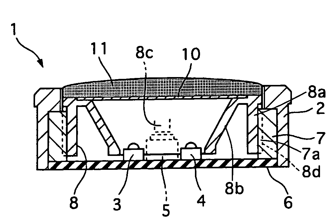
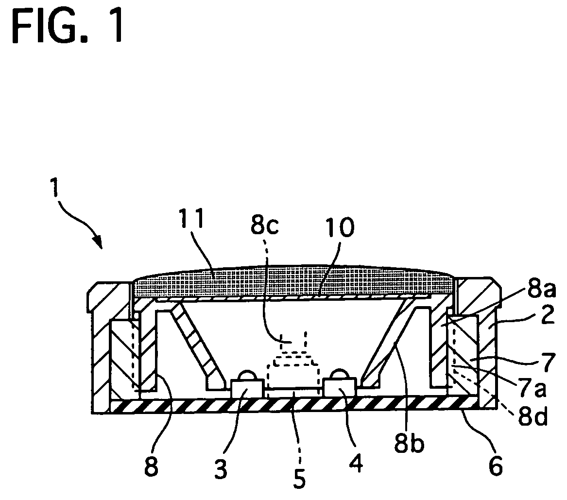
[0063]The operation of the switch 1 with the display device of the first embodiment will be described.

[0064]The display device of the first embodiment can be shifted between a nondisplay mode and two display character appearing modes.

[0065]When the ultraviolet light source 3 and the red light source 4 are controlled to be turned off as shown in FIG. 6A, no light is emitted from them and therefore no display characters appears, so that the user can not see it from the exterior of the switch 1 through the smoked lens 11. In this case, the smoked lens 11 suppresses both of the color light and the ultraviolet light included in incoming light and its reflected light, when the incoming light comes into an interior of the display device from the exterior of the switch 1 and when the incoming light is reflected inside of the display device to go toward the filter 10 as the reflected light.

[0066]Specifically, the smoked lens 11 suppresses the color light and the ultraviolet light contained i...

second embodiment

[0090]Next, a display device of a second embodiment according to the present invention will be described with reference to the accompanying drawings of FIGS. 9 to 21C.

[0091]Referring to FIGS. 9 to 11, there is shown a display device of the second embodiment, adapted for a switch 1.

[0092]The switch 1 is provided with a switch finisher 2, a guide member 7 fixed to a lower and inner part of the switch finisher 2, a slider 8 arranged inside of the switch finisher 8 and capable of sliding rearward and forward, corresponding to downward and upward in FIG. 9, respectively, and a display device arranged within the switch finisher 2.

[0093]The display device has an ultraviolet light source 3, a red light source 4, a blue light source 9, a filter 10, and a smoked lens 11 so that it can selectively appear three display characters, a third display character “A” in red as indicated by a reference number 14 in FIG. 13A, a fourth display character “E” in blue as indicated by a reference number 15 i...


PUM


Abstract

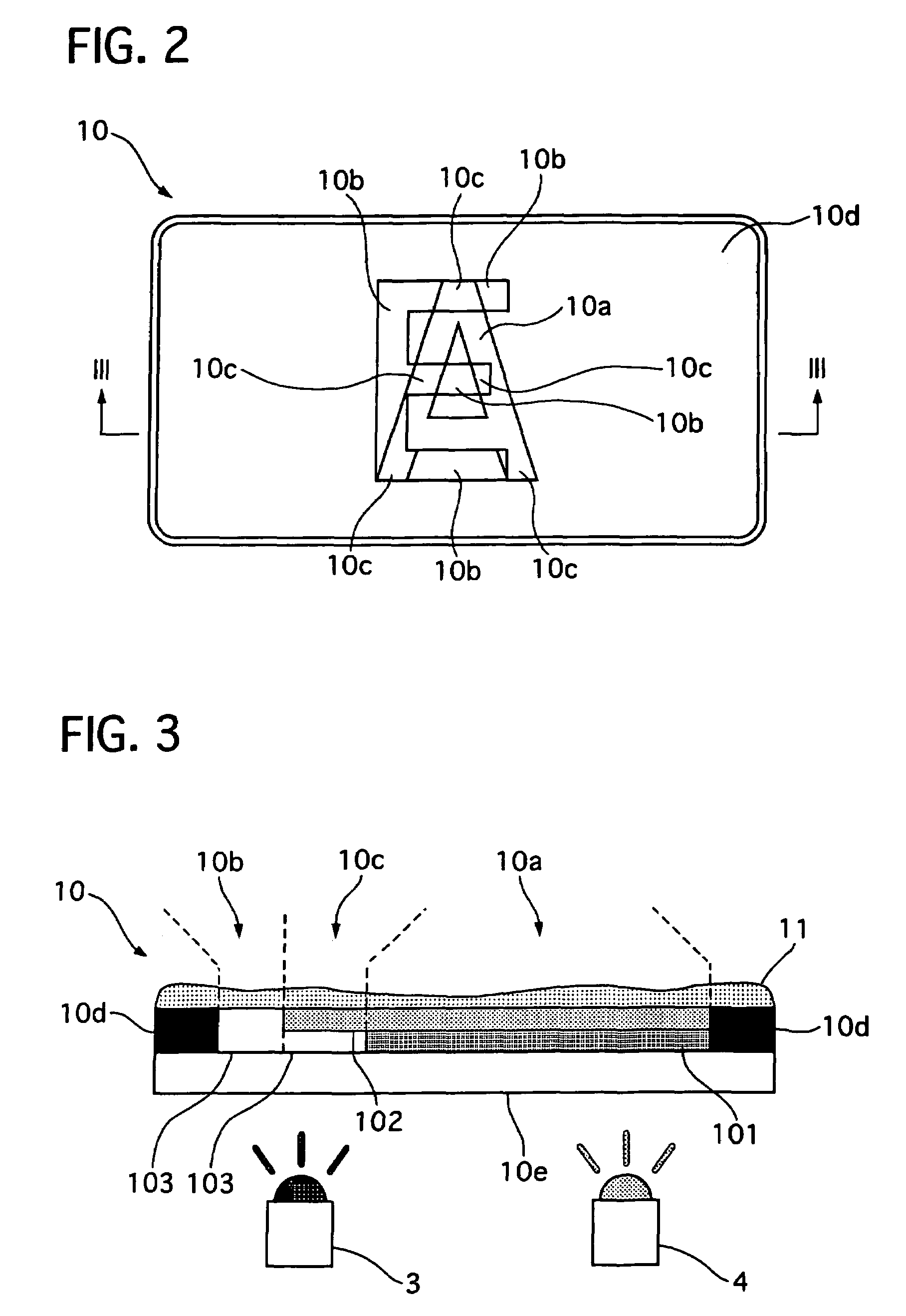
A display device includes an ultraviolet light source, a color light source, and a filter selectively hit by their lights. The filter has a first area part for displaying the first display contents excluding an overlapped parts when the ultraviolet light is emitted, a second area part for the second display contents excluding the overlapped parts when the color light is emitted, and a third display part for displaying the overlapped parts when one of the ultraviolet and color light is emitted. The first area part blocks the color light and produces visible light when the ultraviolet light hits the first area part, the second area part allows the ultraviolet and color lights to pass therethrough, and the third area part allows the ultraviolet and color lights to pass therethrough and produces the visible light when the ultraviolet light hits the third area part.

Description

BACKGROUND OF THE INVENTION[0001]1. Field of the Invention[0002]The present invention relates to a display device that is capable of shifting display contents having different colors and an overlapped part thereof.[0003]2. Description of the Related Art[0004]A display device of this kind is disclosed in Japanese patent laying-open publication No. 2001-100679. This display device has a first printed area part through which only blue light can pass and a second printed area part through which only green light can pass, the other printed area part to form a lightproof background, and a non-printed area part through which the blue light and the green light can pass. The first, second printed area parts and the other printed area part are formed by printing on a rear surface of a transparent sheet, which can be illuminated from a rear side thereof selectively by a first light source for emitting the blue light and a second light source for emitting the green light. When the first light s...

Claims


Application Information

Patent Timeline
Patent Type & Authority Patents(United States)
IPC IPC(8): G09F13/00B60Q1/26F21V11/00G09F13/12G09F9/00G09F19/00F21V9/00G01D11/28G08B5/00G08B5/36
CPCG09F19/12G09F13/22
Inventor EGAMI, SHIGERUARAI, KAZUO
Owner CALSONIC KANSEI CORP
Learn More