

Cylindrical vibration isolating device
a technology of isolating device and cylindrical shaft, which is applied in the direction of machine supports, shock absorbers, and spring/damper functional characteristics, etc., can solve the problems of excessive increase of the constant of the spring in the axially perpendicular direction, and the layout becomes difficult, so as to prevent the axial expansion of the device, increase the degree of freedom of spring constant ratio control, and increase the freedom of layout
- Summary
- Abstract
- Description
- Claims
- Application Information
AI Technical Summary
Benefits of technology
Problems solved by technology
Method used
Image

Examples
Embodiment Construction
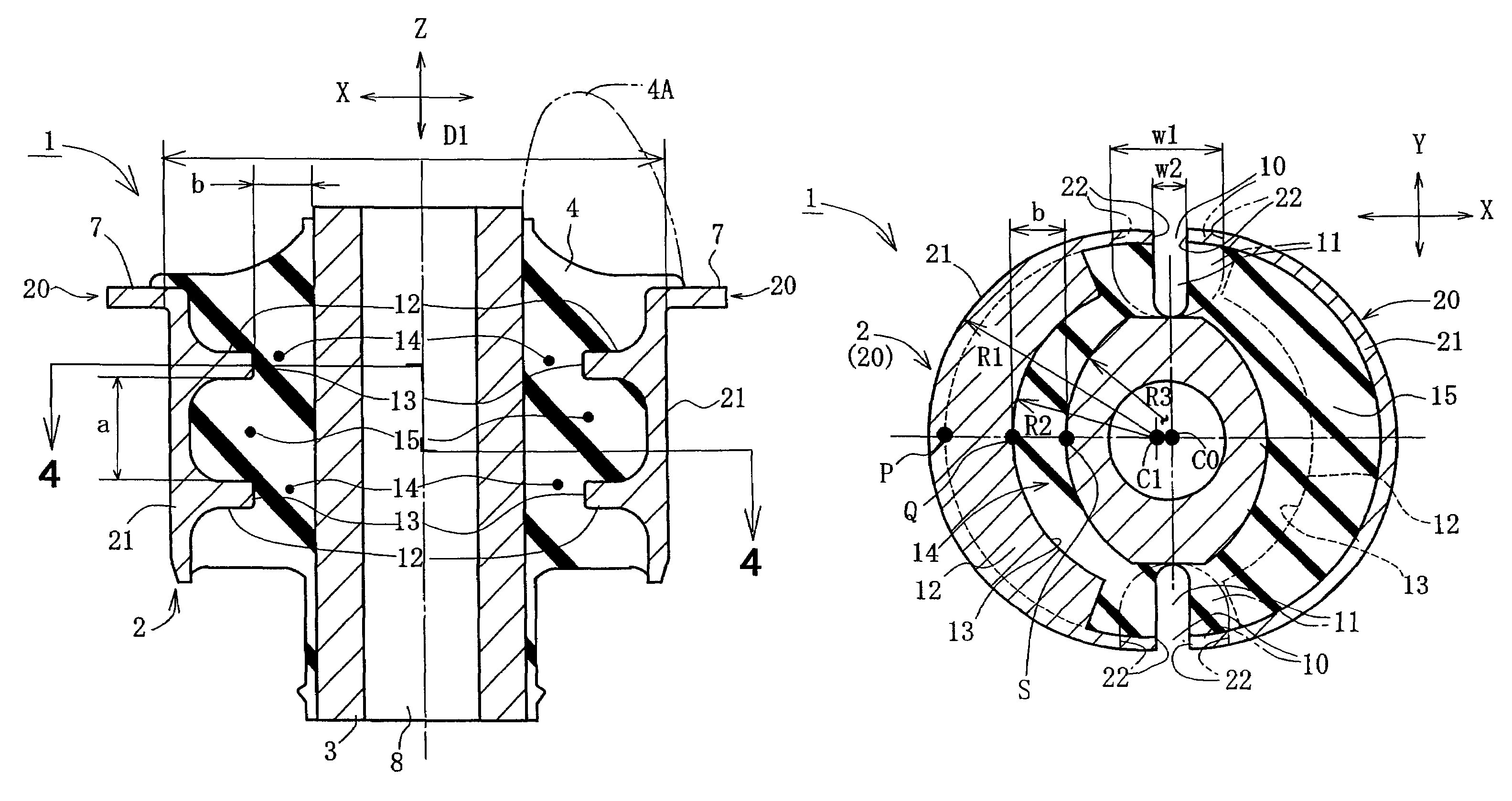
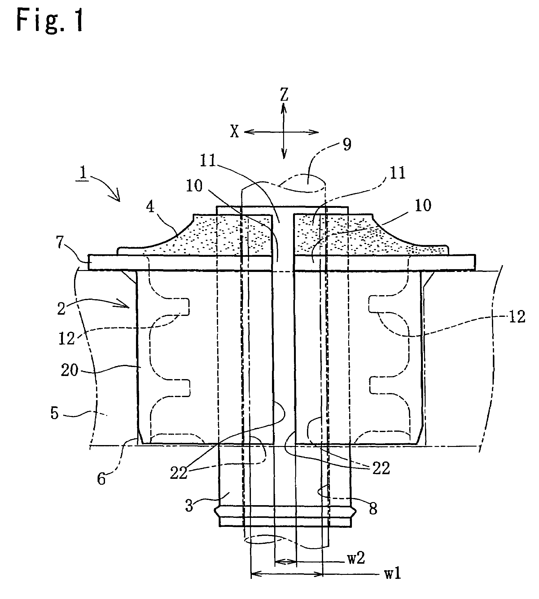
[0026]Hereinafter, the embodiment embodied in a sub-frame mount will be explained with reference to the accompanying drawings. FIG. 1 is a side view of a sub-frame. FIG. 2 is a plan view thereof. Referring now to these drawings, the sub-frame mount 1 comprises an outer cylinder 2, an inner cylinder 3 substantially concentrically arranged within the outer cylinder 2, and a vibration isolating rubber 4 connecting between these inner and outer cylinders. The vibration isolating rubber 4 is a principal portion for absorbing the vibration and formed of a conventional rubber as an example of an elastic body. The outer cylinder 2 and the inner cylinder 3 are formed by a proper method such as casting or the like, using a proper material consisting of metal or resin.
[0027]The outer cylinder 2 is installed by being pressed into a mounting hole 6 provided on a sub-frame 5 on a vehicle body side. The reference character 7 is a flange provided on an end of the outer cylinder 2 to be fitted on a ...
PUM
 Abstract
Description
Claims
Application Information