Display device for exterior rearview mirror

a display device and rearview mirror technology, applied in signalling/lighting devices, vehicle components, optical viewing, etc., can solve the problems of difficult determination of the driver inability to view the turn signal visual indicators of the host vehicle, etc., to facilitate the assembly process, facilitate the connection, and facilitate the connection

Inactive Publication Date: 2009-09-01
MAGNA MIRRORS OF AMERICA INC
View PDF104 Cites 436 Cited by
  • Summary
  • Abstract
  • Description
  • Claims
  • Application Information

AI Technical Summary

Benefits of technology

[0017]Therefore, the present invention provides a display device or indicator at the back plate of a mirror reflector sub-assembly. The mirror reflector sub-assembly thus may achieve enhanced assembly processes, and may be supplied or provided to a mirror manufacturer or assembler as a unit that includes the indicator mounting portion (and that may also include the indicator) and display. The integrally formed back plate and indicator mount or mounting portion may be readily attached to the mirror reflective element, and the indicator may be readily plugged into or connected to or received in the indicator mount to assemble the mirror reflector sub-assembly. The back plate may include one or more indicator mounts or mounting portions for providing one or more displays at the reflective element, such as a blind spot / LCA display and / or a turn signal display and / or the like.

Problems solved by technology

It is known to provide an object in a blind spot detection / LCA system for a vehicle that detects the presence of another vehicle or object in the lane next to the host vehicle, where it may be difficult for the driver of the host vehicle to determine whether or not there is another vehicle or object adjacent to the host vehicle.
It is desirable that such turn signal visual indicators are not readily viewable by the driver of the host vehicle when they are activated.
Somewhat costly and complicated indicator constructions have been contemplated that, when placed behind and supported by the mirror reflective element, attempt to have their projected beam of emitted light directed principally to be viewed by the driver of the host vehicle (or other person external to the host vehicle for turn signal applications) through the mirror reflective element and shielded from view by other drivers (or from the driver of the host vehicle for turn signal applications).

Method used


Image

  • Display device for exterior rearview mirror
  • Display device for exterior rearview mirror
  • Display device for exterior rearview mirror

Examples


Embodiment Construction

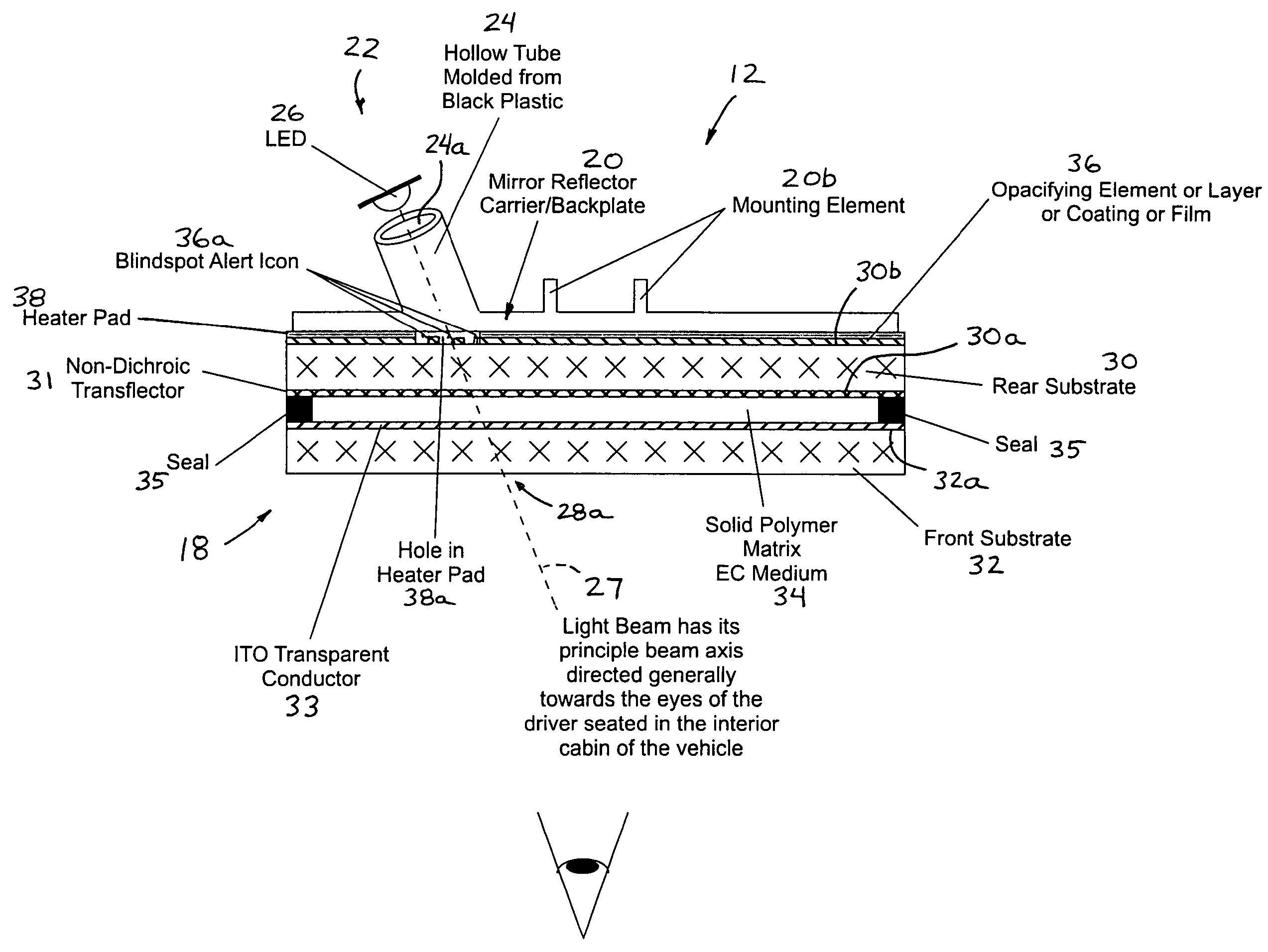
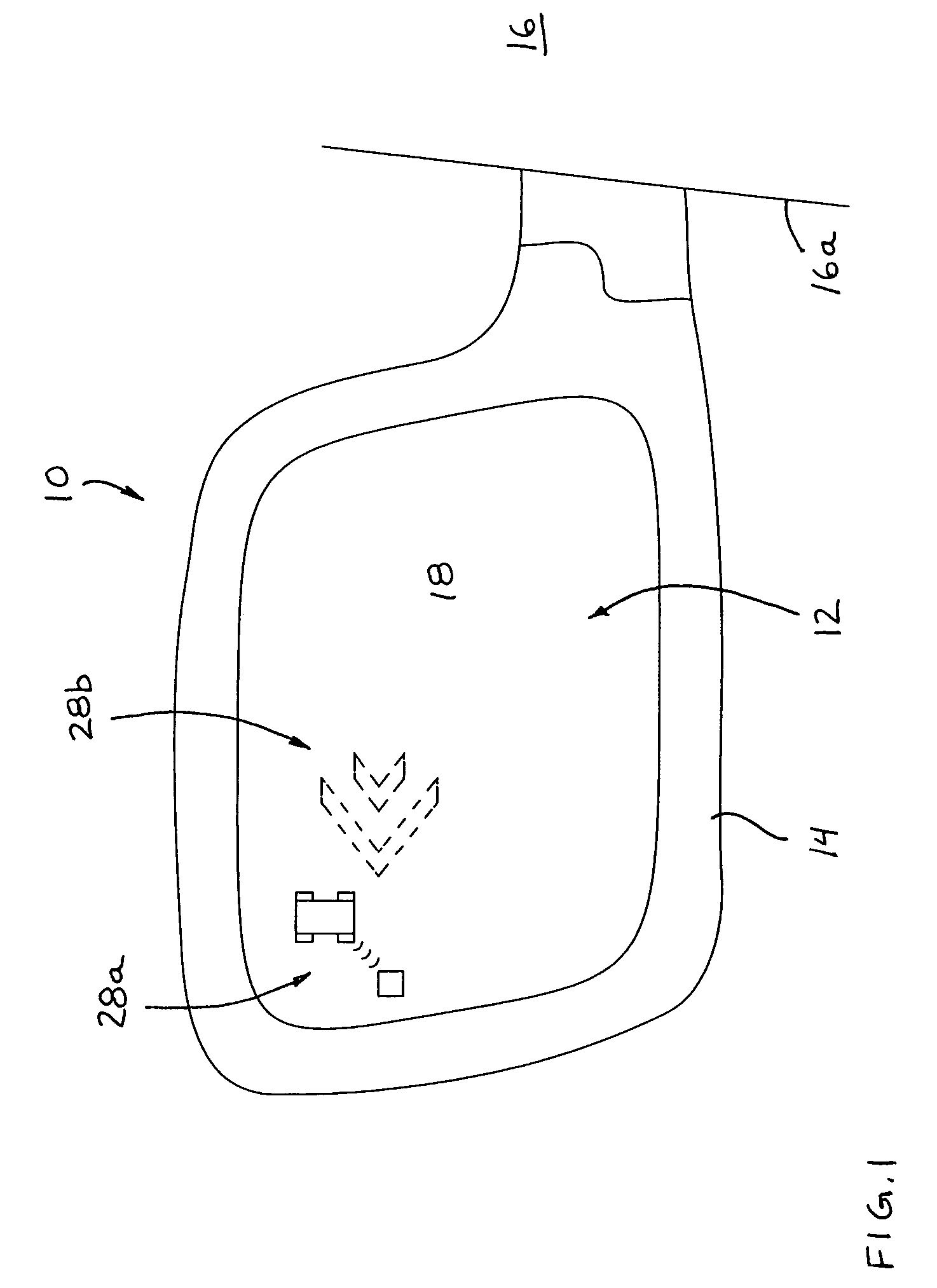
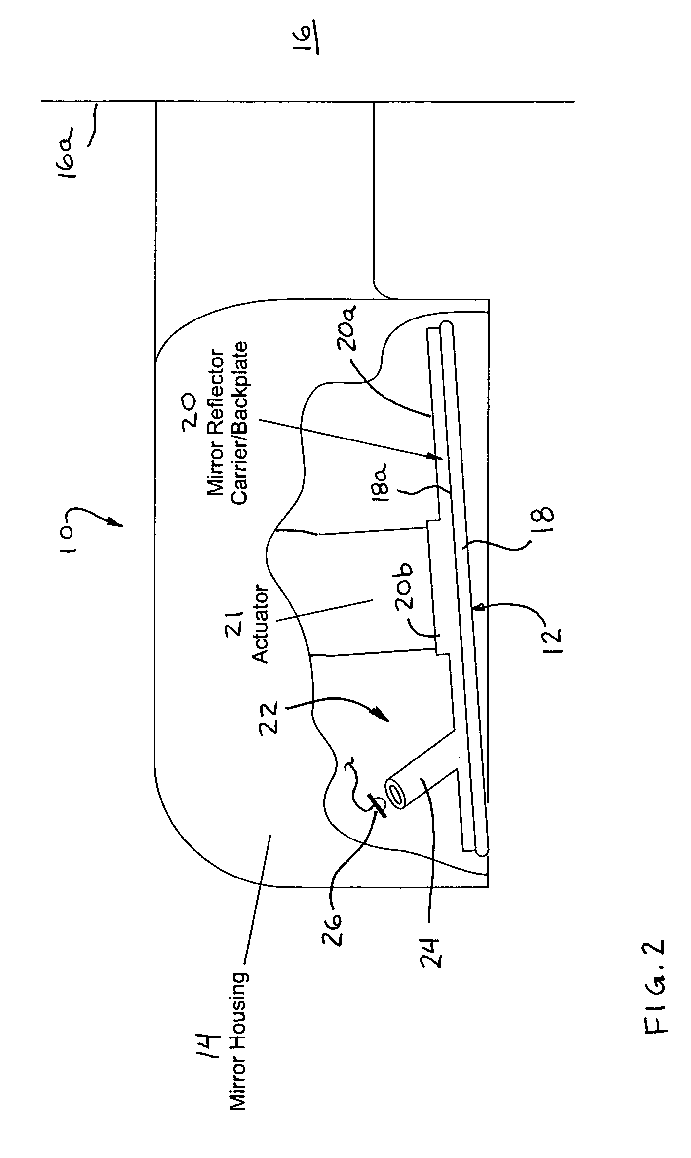
[0039]Referring now to the drawings and the illustrative embodiments depicted therein, an exterior rearview mirror assembly 10 for a vehicle includes a mirror reflector sub-assembly 12 and a mirror shell or casing 14 (FIG. 1). Mirror assembly 10 is mounted at the side 16a of a host or subject vehicle 16. As shown in FIG. 2, mirror reflector sub-assembly 12 includes a mirror reflective element 18 and a mirror reflector carrier or back plate 20 attached to or mounted to or adhered to a rear surface 18a of mirror reflective element 18. Mirror assembly 10 includes a display element or device 22 that is operable to provide a display or indication at the reflective element for viewing the display or indication through the mirror reflective element. Display device 22 includes a generally hollow indicator mounting portion or indicator receiving portion or extension or tube 24 (that extends rearwardly from a rear surface 20a of back plate 20 so as to extend generally away from the mirror ref...


PUM


Abstract

An exterior mirror sub-assembly includes a reflective element, a back plate, and a display element having a light source that is activatable to emit light. The display element attaches to a display receiving portion of the back plate and the light source is activatable to emit light through the display receiving portion. The display receiving portion may be configured to orient the display element at a predetermined angle so that light exiting the display element when the light source is activated may be directed (a) generally away from the vehicle when the mirror assembly is mounted to the vehicle so as to be principally viewed by drivers of other vehicles or (b) generally toward the driver of the vehicle when the mirror assembly is mounted to the vehicle so as to be principally viewed by the driver of the host vehicle.

Description

CROSS REFERENCE TO RELATED APPLICATION[0001]The present claims the benefit of U.S. provisional application, Ser. No. 60 / 717,093, filed Sep. 14, 2005, which is hereby incorporated herein by reference in its entirety.FIELD OF THE INVENTION[0002]The present invention relates to exterior rearview mirror assemblies and, more particularly, to an exterior rearview mirror assembly having a blind spot / object detection indicator and / or a lane change aid (LCA) indicator and / or a turn signal or indicator at the exterior rearview mirror assembly.BACKGROUND OF THE INVENTION[0003]It is known to provide an object in a blind spot detection / LCA system for a vehicle that detects the presence of another vehicle or object in the lane next to the host vehicle, where it may be difficult for the driver of the host vehicle to determine whether or not there is another vehicle or object adjacent to the host vehicle. Such an object in a blind spot detection / LCA system often includes a visual indicator that vis...

Claims


Application Information

Patent Timeline
Patent Type & Authority Patents(United States)
IPC IPC(8): B60Q1/26B60Q1/00B60R1/12
CPCB60Q1/2665B60R1/1207B60Q1/26B60R2001/1215B60Q1/0023B60R1/0602B60R1/088B60R2001/1284B60R2001/1223
Inventor LYNAM, NIALL R
Owner MAGNA MIRRORS OF AMERICA INC
Why Eureka
Try Eureka