
Longitudinal shaft

a longitudinal shaft and longitudinal shaft technology, applied in the direction of yielding coupling, control device, rotary machine parts, etc., can solve the problems of large centripetal force, vibration, disruptive noise, etc., and achieve the effect of reducing the danger to passengers in the passenger compartment of the vehicle, resulting from the longitudinal sha

Inactive Publication Date: 2009-09-01
SHAFT FORM ENG GMBH
View PDF19 Cites 1 Cited by
  • Summary
  • Abstract
  • Description
  • Claims
  • Application Information

AI Technical Summary

Benefits of technology

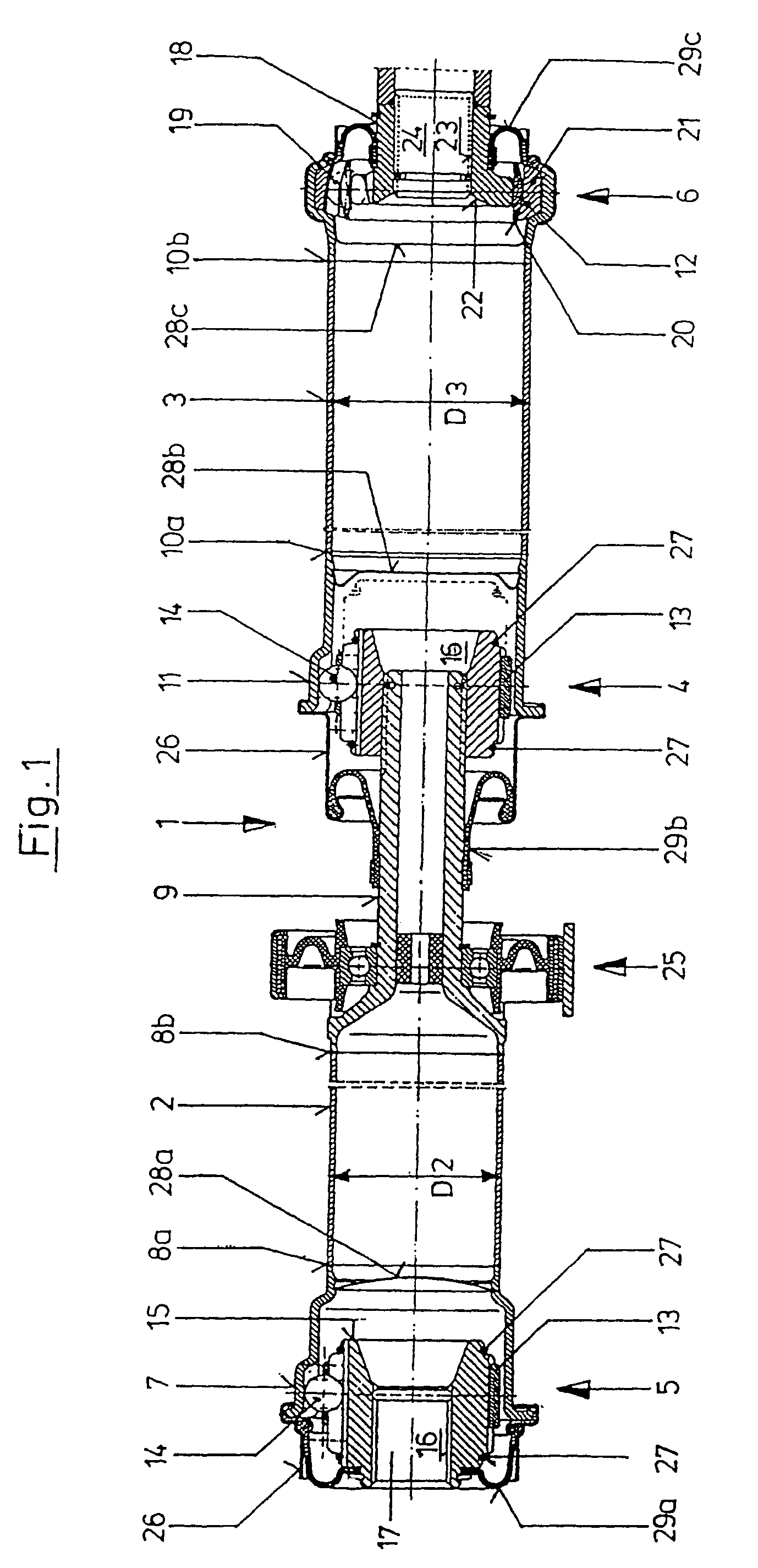
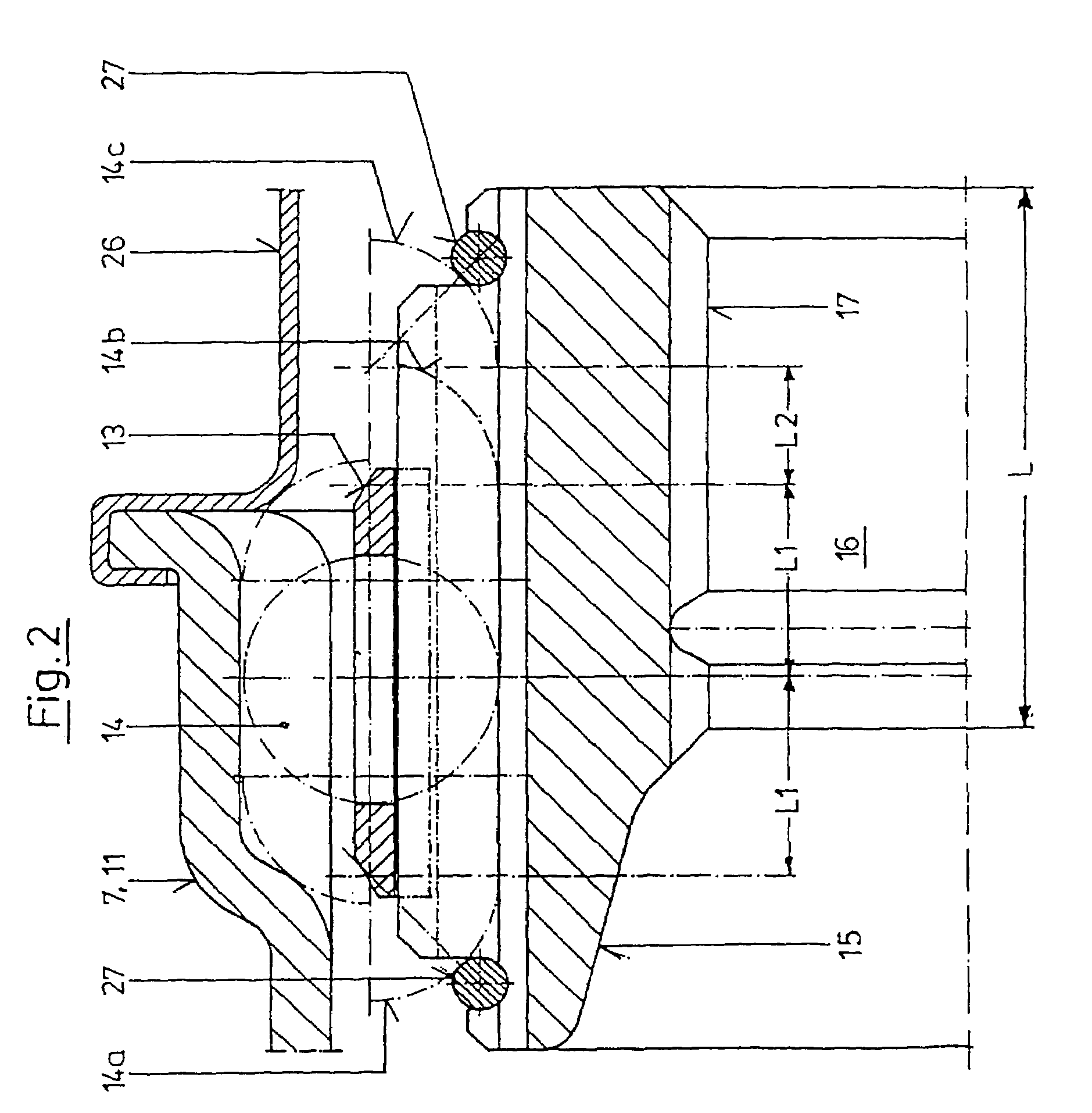
[0008]This task is accomplished, according to the invention, in that the inner hubs of the gearbox-side articulation as well as of the differential-side articulation have a central bore provided with a plug-in tooth system, to connect the longitudinal shaft for integral rotation, and to center it, on journals of a gearbox output shaft and a differential input shaft, respectively. In this connection, the invention is based on the idea that the centering diameter of a plug-in connection between the inner hub of the gearbox-side articulation and of the differential-side articulation with the gearbox output shaft and the differential input shaft, respectively, which diameter is clearly smaller as compared with flange centering, allows a significant reduction in the unbalance of the longitudinal shaft, at the same quality of tolerance. In this manner, the centripetal forces caused by the unbalance are also reduced, thereby increasing the comfort of the vehicle, by means of lower vibrations and noises of the drive train. The connection between the gearbox output shaft and the differential input shaft by means of the longitudinal shaft takes place, in this connection, in that the profiled inner hub of the gearbox-side articulation of the longitudinal shaft is set onto a correspondingly profiled journal of the gearbox output shaft, and the inner hub of the differential-side articulation is pushed onto a journal of the differential input shaft. In this manner, not only is a connection between the gearbox output shaft and the differential input shaft that permits integral rotation produced, but also centering of the longitudinal shaft is achieved.
[0009]The centering of the two segments of the longitudinal shaft by way of the central articulation can be improved if the central articulation also has an inner hub having a central bore that is provided with a plug-in tooth system, which accommodates a corresponding journal of a shaft segment of the longitudinal shaft for plug-in centering for integral rotation. Here, the connection between the two segments of the longitudinal shaft in the central articulation takes place in essentially the same manner as the connection of the gearbox output shaft and the differential input shaft to the longitudinal shaft.
[0010]In a further development of the idea of the invention, it is provided that the two shaft segments of the longitudinal shaft are configured as shaft tubes, and the outer hubs of the gearbox-side articulation, the differential-side articulation, and the central articulation are shaped sheet-metal parts directly connected with the shaft tubes. The greatest possible use of shaped sheet-metal parts in the articulations of the longitudinal shaft, which are connected directly to the longitudinal shaft tubes by way of a weld seam, for example, reduce the overall weight of the longitudinal shaft. Minimization of the weight of the longitudinal shaft also contributes to reducing the centripetal forces that occur, along with the improved centering.
[0012]If the gearbox-side articulation and the central articulation are configured as sliding articulations and have a common installation / displacement path, which corresponds at least to a length such that the gearbox output shaft or the differential input shaft projects into the inner hub of the gearbox-side articulation or the differential-side articulation, respectively, in operation, the longitudinal shaft according to the invention can be installed in particularly simple manner, between the gearbox output shaft and the differential input shaft.
[0014]According to a preferred embodiment of the invention, the gearbox side shaft segment of the longitudinal shaft has a diameter that differs from that of the differential-side shaft segment, in such manner that the two shaft segments can be pushed onto one another in the manner of a telescope. With this embodiment of the longitudinal shaft, it is avoided that the longitudinal shaft will bend out when compressed end to end, for example as the result of an accident, and penetrate into the passenger compartment of the vehicle. Instead, if in-line compression occurs, the two shaft segments of the longitudinal shaft will move into one another in the manner of a telescope, so that danger to the passengers in the passenger compartment of the vehicle, resulting from the longitudinal shaft, is reduced.

Problems solved by technology

However, in the case of the high speeds of rotation of the longitudinal shaft that frequently occur during operation, between 8,000 and 10,000 revolutions per minute, even slight balance errors of the longitudinal shaft resulting from insufficient centering will bring about great centripetal forces in the longitudinal shaft, which result in vibrations and disruptive noises.

Method used


Image

  • Longitudinal shaft
  • Longitudinal shaft
  • Longitudinal shaft

Examples


Embodiment Construction

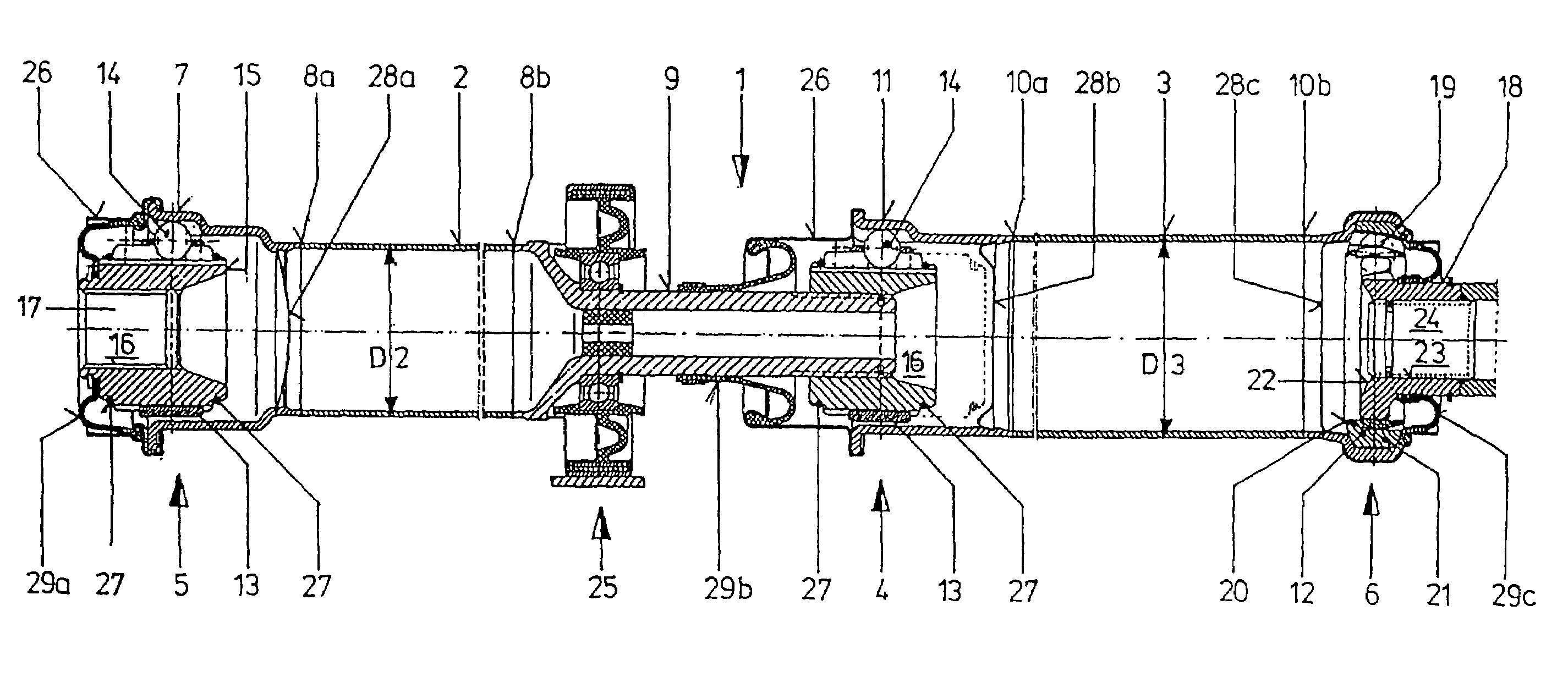
[0020]The gearbox-side shaft segment 2 of the longitudinal shaft 1 ends, on its side facing away from the central articulation 4, in a gearbox-side articulation 5, while the second shaft segment 3 has a differential-side articulation 6 at its end facing away from the central articulation 4. The shaft segments 2 and 3 are configured as sheet-metal tubes, whereby the tube that forms the gearbox-side shaft segment 2 of the longitudinal shaft 1 is connected with the outer hub 7 of the gearbox-side articulation 5, which hub is configured as a shaped sheet-metal part, by way of weld seams 8a, 8b, and is welded to a hollow shaft journal 9 on its side facing the central articulation 4. The tube that forms the differential-side shaft segment 3 of the longitudinal shaft 1 is connected with the outer hub 11 of the central articulation 4, or the outer hub 12 of the differential-side articulation 6, respectively, which are both configured as shaped sheet-metal parts, by way of weld seams 10a and...


PUM


Abstract

A longitudinal shaft for use in particular in four-wheel drive or rear-wheel drive motor vehicles includes a gearbox-side articulation, a differential-side articulation, as well as a central articulation through which a gearbox-side section is integrally linked in rotation to a differential-side section of the longitudinal shaft. To reduce the centrifugal forces occurring at the longitudinal shaft 1 in operation, the gearbox-side articulation and the differential-side articulation have each an inner hub designed to connect the longitudinal shaft integrally in rotation respectively to a gearbox output shaft and to a differential input shaft, the longitudinal shaft being centered on the gearbox output shaft and the differential input shaft by interlocking through the inner hubs.

Description

CROSS REFERENCE TO RELATED APPLICATIONS[0001]Applicant claims priority under 35 U.S.C. §119 of German Application No. 102 37 172.5 filed Aug. 14, 2002. Applicant also claims priority under 35 U.S.C. §365 of PCT / EP2003 / 007386 filed Jul. 9, 2003. The international application under PCT article 21 (2) was not published in English.BACKGROUND OF THE INVENTION[0002]1. Field of the Invention[0003]The invention relates to a longitudinal shaft, particularly for use in automobiles having all-wheel drive or rear-wheel drive, comprising a gearbox-side articulation, a differential-side articulation, and a central articulation, each of which have an inner hub and an outer hub that surrounds the former at least in some regions, whereby two shaft segments are connected with one another so as to rotate together, by way of the central articulation. In this connection, the terms “gearbox-side” and “differential-side” are used merely as examples in the sense of this invention, to differentiate the two ...

Claims


Application Information

Patent Timeline
Patent Type & Authority Patents(United States)
IPC IPC(8): F16D3/227B60K17/22B60K17/24F16D3/06
CPCB60K17/22F16D3/065B60K17/24Y10S464/906F16D2003/22306
Inventor JACOB, WERNER
Owner SHAFT FORM ENG GMBH
Learn More