Autostereoscopic display

a technology of autostereoscopic display and display screen, which is applied in the field of system for providing a stereoscopic view, to achieve the effects of reducing the accuracy of the lens array, high technical skill, and reducing production costs

Active Publication Date: 2009-09-01
PANASONIC LIQUID CRYSTAL DISPLAY CO LTD +1
View PDF8 Cites 7 Cited by
  • Summary
  • Abstract
  • Description
  • Claims
  • Application Information

AI Technical Summary

Benefits of technology

[0010]For instance, when one lens is to be assigned to “m×n” pixels, the lens pitch in lateral direction must be “mp” and the lens pitch in longitudinal direction must be “nq” if pixel size is “p×q” [μm]. In the liquid crystal display currently in use, the unit of accuracy of “mp” and “nq” must be in the unit of 1 μm or 0.1 μm. To manufacture a lens array with such accuracy, very high technical skill is needed, and this leads to higher production cost.
[0011]It is possible to produce the lens array at lower cost by decreasing the accuracy. When such lens array is used, there arises a problem that a stereoscopic image cannot be correctly displayed.

Problems solved by technology

There is also a problem in that a position of a pixel display is to be obtained as original information for the positioning.

Method used


Image

  • Autostereoscopic display
  • Autostereoscopic display
  • Autostereoscopic display

Examples


embodiment 1

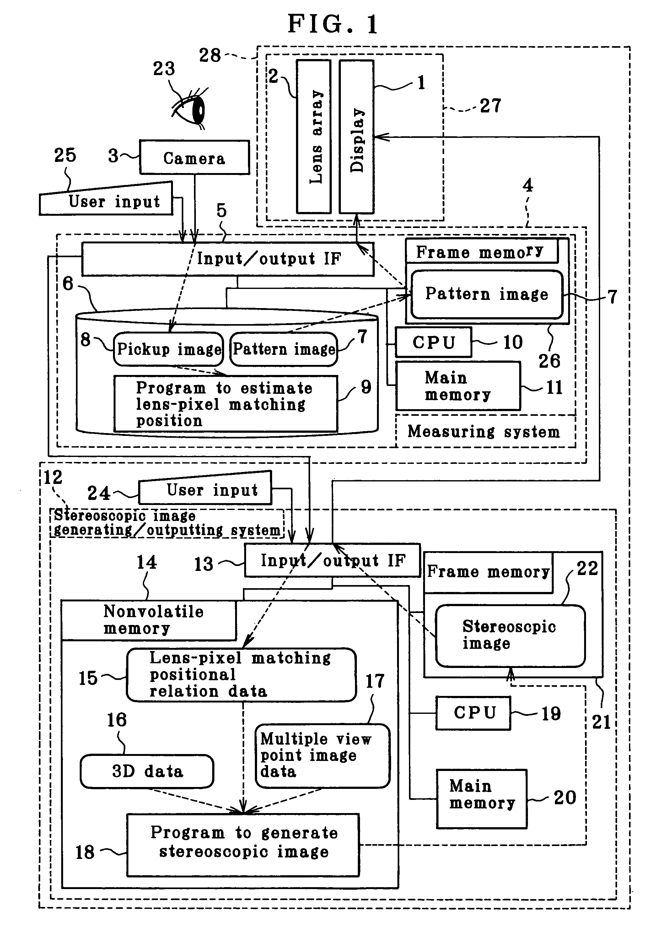
[0035]FIG. 1 is a block diagram of Embodiment 1. In the figure, a dotted arrow mark shows a conceptual data flow. A stereoscopic display 27 is a combination of a display 1 for displaying an ordinary type 2-dimensional image and a convex lens array 2. An observer 23 observes the stereoscopic display 27 from the direction of the convex lens array 2.

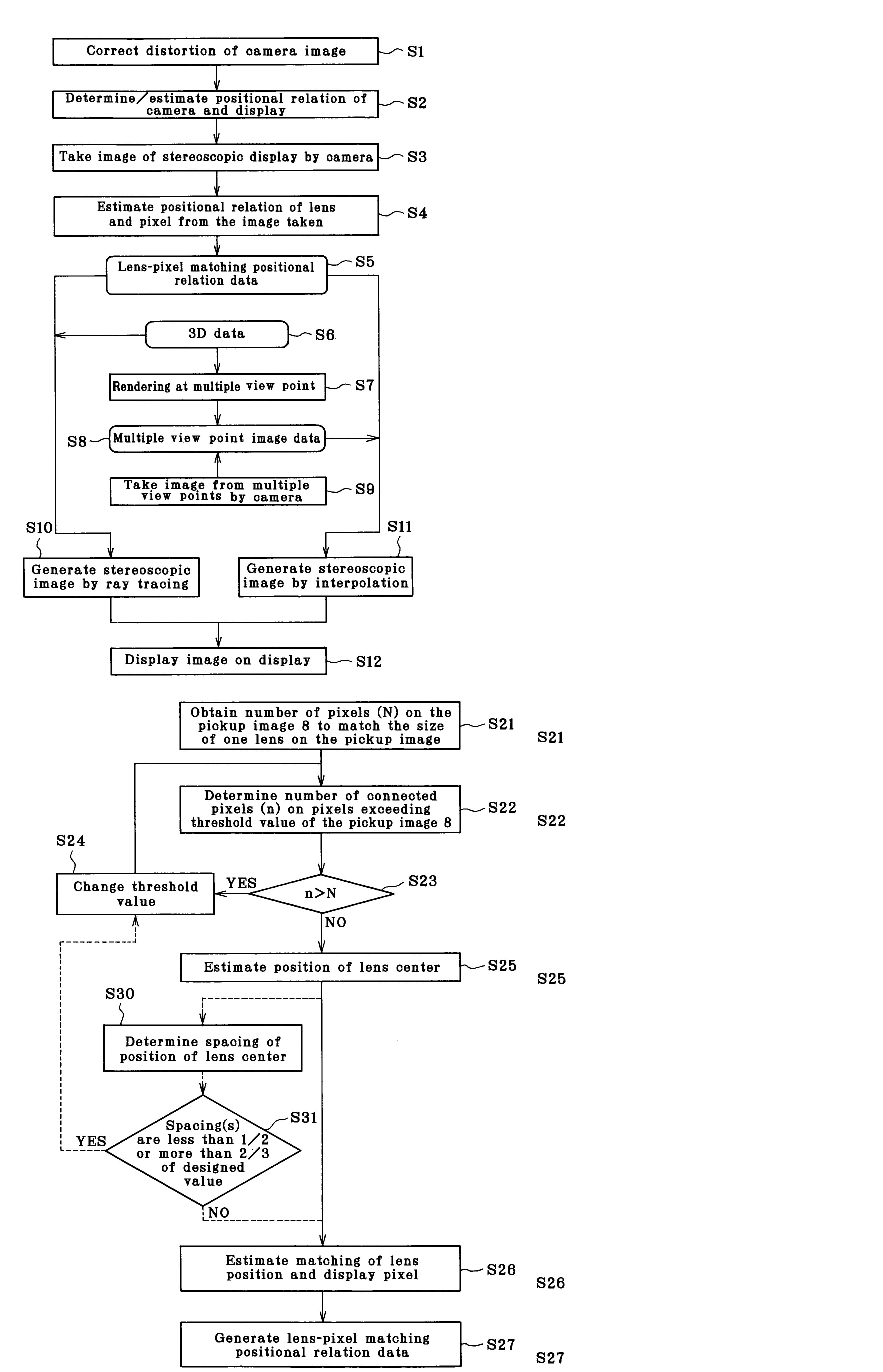
[0036]First, relation between lens and pixel on the stereoscopic display 27 is obtained by using a measuring system 4. In a storage unit 6 of the measuring system 4, a pattern image 7 for measurement is stored. In response to an input from a user input unit 25, the pattern image 7 is loaded to a frame memory 26 via OS (operating system), and the pattern image 7 is displayed on the display 1 via an input / output IF (interface).

[0037]A camera 3 is used to take the image displayed on the display 1 via the lens array 2. The image thus taken is stored in the storage unit 6 via the input / output IF 5 as a pickup image 8. Then, a program 9 to estima...

embodiment 2

[0094]As Embodiment 2, description will be given on a case where the multiple viewpoint image data 17 is generated from the 3D data 16 in the flow chart of FIG. 3 and a stereoscopic image is approximately generated.

[0095]The multiple viewpoint image data 17 is prepared by the rendering as an image of two or more viewpoints from the 3D data 16 (Step S7). Description will be given on an embodiment of this rendering referring to FIG. 10. In this embodiment, parallel projections are used by assuming that the viewpoint is at infinity. The projection plane is fixed to facilitate the generation of the stereoscopic image.

[0096]First, in FIG. 10, a projection plane 60 is determined to match with the resolution of the display. Next, based on the 3D data 16, a 3-dimensional object 57 is placed at a position where the stereoscopic display is to be given.

[0097]Parallel rays 63 in projecting direction 62 as designated are defined for each pixel 61 on the projection plane 60. Color and brightness ...

embodiment 3

[0110]As Embodiment 3, description will be given below on a case where the stereoscopic image is generated by approximately using interpolation (Step S11) from the multiple viewpoint image data 17 acquired by image-taking at multiple viewpoints (Step S9) using a multi-camera in the flow chart of FIG. 3 by referring to FIG. 11.

[0111]In order to facilitate the explanation on the image-taking in Step S9 of FIG. 3, description will be given now on a model, in which an object 70 shown in FIG. 11 is taken by two cameras.

[0112]For each of the cameras, distortion is corrected in advance, and it is assumed that the image is taken as perspective projection from the ideal viewpoint. It is assumed that the ideal viewpoint of the camera at a standard camera position is 71 and an optical axis is 79. The projection plane is regarded as 72 from the field angle of the camera, and it is supposed that the surface of the object 70 closer to the ideal viewpoint is projected.

[0113]In contrast to this cam...


PUM


Abstract

In a stereoscopic display system, comprising a display and a lens array, it is difficult to manufacture the lens array with lens spacing at high accuracy as designed, and it is also difficult to attain high installation accuracy when the display and the lens array are combined together.An image of a stereoscopic display 27 with a display 1 and a lens array 2 integrated with each other is taken by a camera 3, and a positional relation of each pixel of the display 1 and each lens center of the lens array 2 is determined by a measuring system 4. Based on the matching positional relation information of the lenses and the pixels thus acquired, a stereoscopic image generating / outputting system 12 generates a stereoscopic image and supplies the image to the stereoscopic display 27.

Description

BACKGROUND OF THE INVENTION[0001]The present invention relates to a system for providing a stereoscopic view. In particular, the invention relates to an autostereoscopic display, by which a user can have a stereoscopic view through naked eyes.[0002]With rapid progress to attain higher resolution of display and with incessant improvement of the technique to manufacture micro-size lenses in recent years, attention in the market is now focused on a stereoscopic display for naked eyes through utilization of integral photography mode (“IP mode”) as described in: M. G. Lippmann: Epreuves reversibles donnant la sensation du relief”, J. de Phys., vol. 7, 4th series, pp. 821-825, November 1908 (hereinafter referred as “Non-Patented Reference 1”). A stereoscopic display system for multiple eyes is also known, which gives stereoscopic effect only in lateral direction by using renticular lens and parallax barrier.[0003]In these stereoscopic display systems, it is important to have accurate posi...

Claims


Application Information

Patent Timeline
Patent Type & Authority Patents(United States)
IPC IPC(8): H04N5/222
CPCG02B27/2214H04N13/0425H04N13/0404H04N13/305H04N13/327G02B30/27
Inventor OIKAWA, MICHIOKOIKE, TAKAFUMIMINAKAWA, TSUYOSHIYAMASAKI, MASAMISAKAI, HIDEYUKI
Owner PANASONIC LIQUID CRYSTAL DISPLAY CO LTD
Why Eureka
Try Eureka