Firearm vise

a technology for firearms and vises, which is applied in the field of firearm holding devices, can solve the problems of many potentially negative features, traditional vises do not hold and support, and damage to firearms from metal jaws, so as to eliminate the possibility of damage to the stock or the mechanism of the firearm, and move easily from one area

Active Publication Date: 2009-09-08
AOB PROD CO
View PDF32 Cites 53 Cited by
  • Summary
  • Abstract
  • Description
  • Claims
  • Application Information

AI Technical Summary

Benefits of technology

[0008]A firearm holding device of the present invention preferably provides at least two points of support along the longitudinal length of the firearm and allows a user to properly secure virtually any type or design of rifle or shotgun. In one embodiment, the firearm holding device uses non-marring synthetic materials to eliminate the possibility of damage to the stock or the mechanism of the firearm. The amount of clamping pressure applied by such holding device to the firearm can be adjusted and limited. The horizontal position of the firearm held in the firearm holding device can be regulated by the use of the various adjustable support components, preferably at the front, middle and rear of the firearm. A firearm holding device of the present invention can be permanently attached to a bench or it can be used as a portable workstation on the flat surface of any table or bench. The firearm holding device is relatively lightweight and can be moved easily from one area to another. One embodiment of a firearm holding device of this invention also incorporates numerous built in storage areas for materials and tools used in the cleaning and maintenance of rifles and shotguns.

Problems solved by technology

While a shop vise can be used to secure a rifle or shotgun and is definitely more secure than holding the firearm with one hand, it has many potentially negative features.
The jaw coverings frequently fall from the vise after installation or are not installed resulting in damage to the firearm from the metal jaws.
A traditional vise does not hold and support a rifle or shotgun at points on both the forend and butt stock simultaneously.
Since a standard vise must clamp on to the firearm at only one point, the pressure at this point to effectively hold and secure the firearm must often be so great that the stock or mechanism of the firearm can be damaged.
Also, most vises sturdy enough to hold a rifle or shotgun are usually quite large and heavy and must be fixedly mounted and attached to a bench.
Such fixedly mounted vises cannot be readily moved from one work area to another.

Method used


Image

  • Firearm vise
  • Firearm vise
  • Firearm vise

Examples


Embodiment Construction

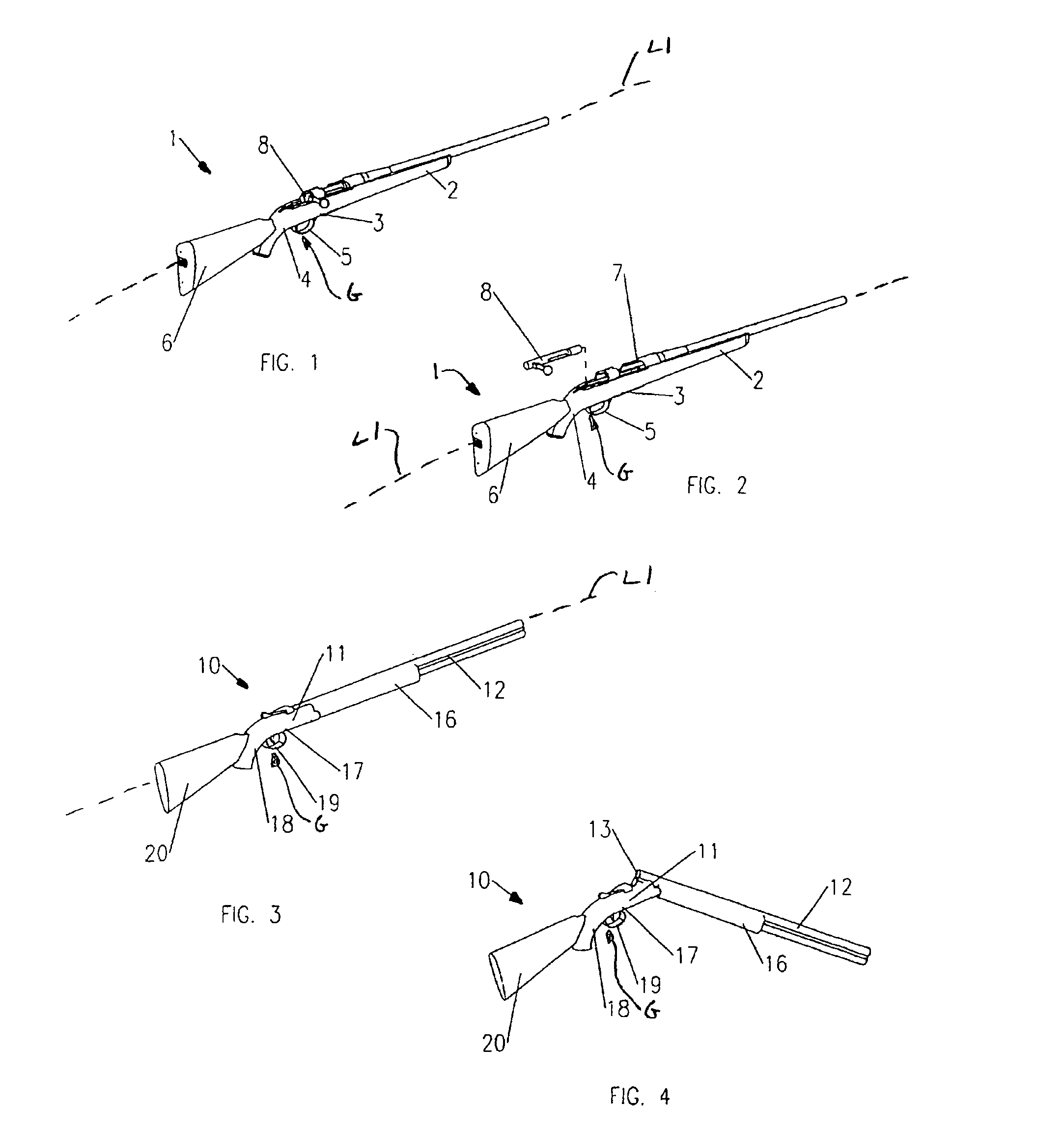
[0043]A firearm holding device of the present invention supports and secures a firearm (e.g., rifle, shotgun, or other firearm) with multi-point support for cleaning or maintenance. Two exemplary firearms that may be supported by the firearm holding device of the present invention include a bolt-action rifle 1 (FIGS. 1 and 2) and a break open sporting shotgun 10 (FIGS. 3 and 4). A typical bolt-action rifle 1, as shown in FIG. 1, is best secured for cleaning, maintenance, or minor repairs by support on at least two of the following three surfaces spaced along the longitudinal axis L1 of the rifle: the stock forend 2; the underside of the stock at a location 3 in front of the trigger guard 5 or at a location 4 behind the trigger guard either or both of these locations 3, 4 being referred to herein as the “grip” G of the firearm; and preferably adjacent the rear of the buttstock 6. Access to the interior 7 of the rifle 1 for cleaning is typically accomplished by removal of the bolt 8 (...


PUM


Abstract

A firearm holding device for holding a firearm having a forend, a grip and a buttstock. The holding device comprises a base having a longitudinal axis, a forend support mounted on the base for supporting the forend of the firearm, a grip support mounted on the base for supporting the grip of the firearm, and a buttstock support mounted on the base for supporting the buttstock of the firearm. At least one of the forend support, grip support and buttstock support are moveable on the base along the longitudinal axis of the base to accommodate various sizes and types of firearms.

Description

CROSS-REFERENCE TO RELATED APPLICATION(S)[0001]This application is a non-provisional of U.S. Provisional Patent Application Ser. No. 60 / 626,689, filed Nov. 10, 2004, which is incorporated herein by reference.BACKGROUND OF THE INVENTION[0002]This invention relates generally to a firearm holding device and more particularly to a device for securely holding a rifle or shotgun for cleaning, maintenance, minor repairs, or mechanical modification.[0003]This invention allows both hands of the user to work with the firearm, as the invention alone will hold and support the firearm in a stable, secure position. In addition, the adjustable features of the various components of the invention enable the user to position virtually any type of rifle or shotgun securely in an optimal position.[0004]Traditionally, a firearm such as a rifle or shotgun is either handheld during cleaning and maintenance or a standard metal machinist vise or shop vise is used to hold the firearm for cleaning or maintena...

Claims


Application Information

Patent Timeline
Patent Type & Authority Patents(United States)
IPC IPC(8): F41A23/16
CPCF41A23/18F41C27/00F41A29/00
Inventor CAULEY, DENNIS
Owner AOB PROD CO
Why Eureka
Try Eureka