
Optical apparatus using flexible printed wiring board

a flexible printed wiring and optical apparatus technology, applied in the direction of television systems, coupling device connections, instruments, etc., can solve the problems of increasing the production cost of the flexible printed wiring board itself, increasing the load on the motor and actuator for the electrical component, and harming the driving accuracy of the electrical component, etc., to achieve low cost, simple structure, and drive stably

Active Publication Date: 2009-09-08
HOYA CORP
View PDF30 Cites 12 Cited by
  • Summary
  • Abstract
  • Description
  • Claims
  • Application Information

AI Technical Summary

Benefits of technology

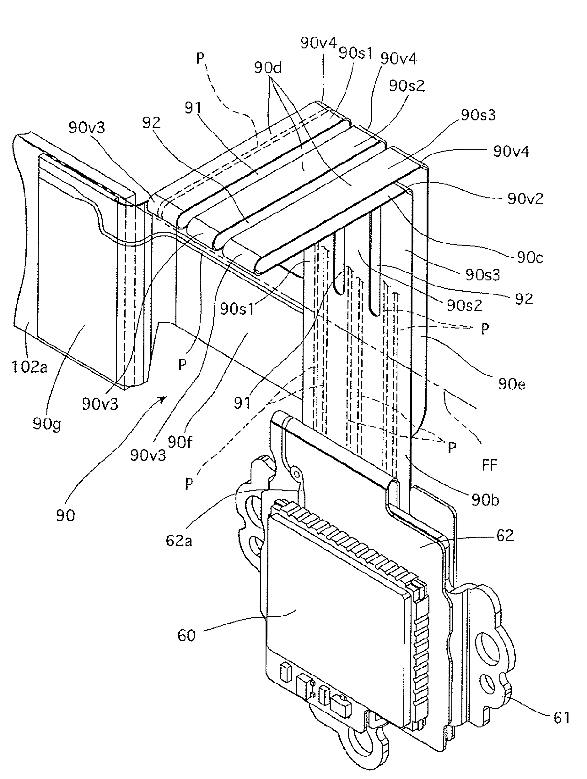
[0007]The present invention provides an optical apparatus containing an electrical component, wherein the electrical component is positioned in an optical system and moves in a plane orthogonal to an optical axis, the electrical component is electrically connected to a stationary board via a flexible printed wiring board, and a resistance in the flexible printed wiring board to movements of the electrical component is reduced by a simple structure at a low cost, while the image pickup device can be driven stably with a high degree of accuracy.
[0019]It is desirable for the slit to have a sufficient width so that each the split portions do not interfere with each other even if twisted in response to movements of the electrical component when the electrical component is moved.
[0023]According to the present invention, an optical apparatus is provided containing an electrical component, wherein the electrical component is positioned in an optical system and moves in a plane orthogonal to an optical axis, the electrical component is electrically connected to a stationary board via a flexible printed wiring board, and a resistance in the flexible printed wiring board to movements of the electrical component is reduced by a simple structure at a low cost, while the image pickup device can be driven stably with a high degree of accuracy.

Problems solved by technology

If this resistance is great, it exerts a harmful effect on the driving accuracy of the electrical component, and the loads on motors and actuators for the electrical component increase.
However, the production cost of the flexible printed wiring board itself increases as the flexible printed wiring board is made of a material having a greater flexibility.

Method used


Image

  • Optical apparatus using flexible printed wiring board
  • Optical apparatus using flexible printed wiring board
  • Optical apparatus using flexible printed wiring board

Examples


Embodiment Construction

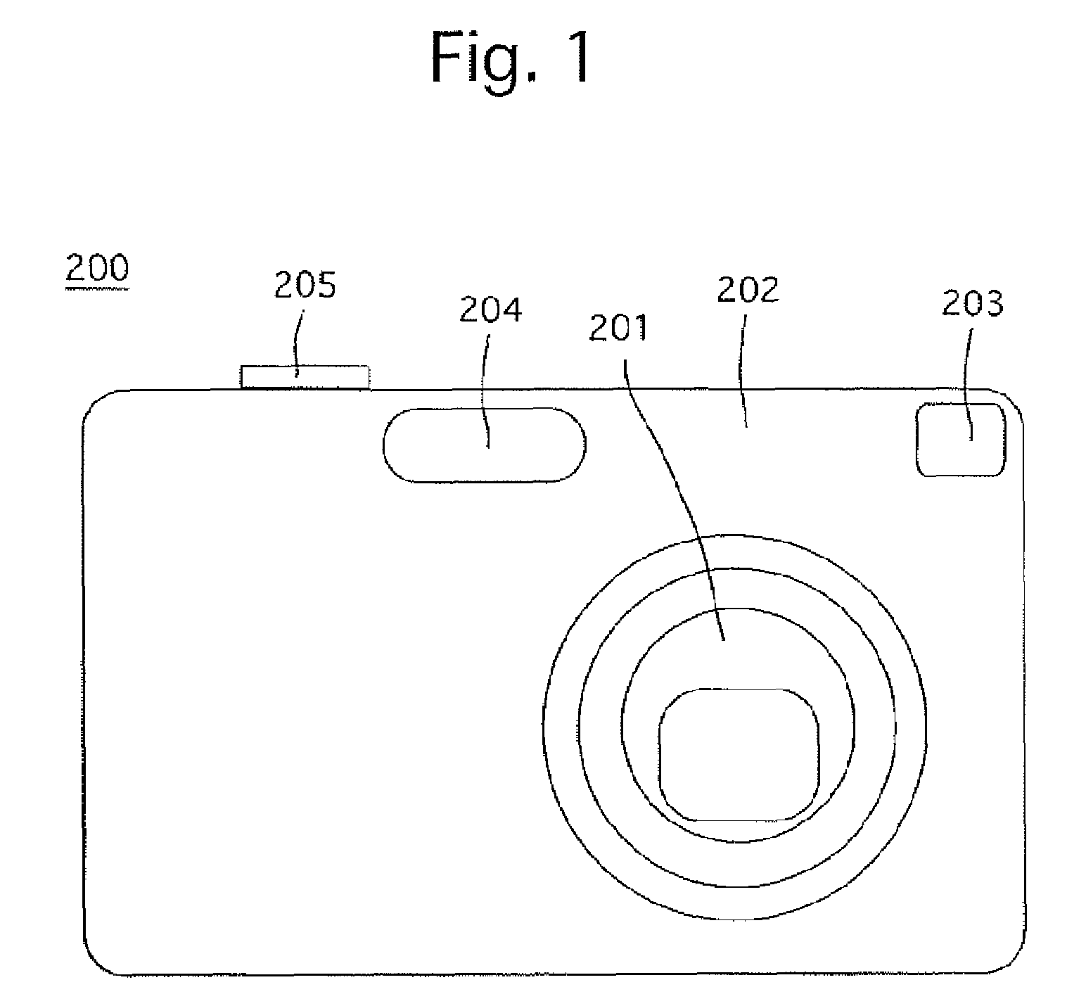
[0055]FIG. 1 shows an outward appearance of a digital camera 200 which incorporates a flexible printed wiring board according to the present invention. The digital camera 200 is provided on the front of a camera body 202 thereof with a zoom lens (zoom lens barrel) 201, an optical viewfinder 203 and a flash 204, and is provided on the top of the camera body 202 with a shutter button 205.

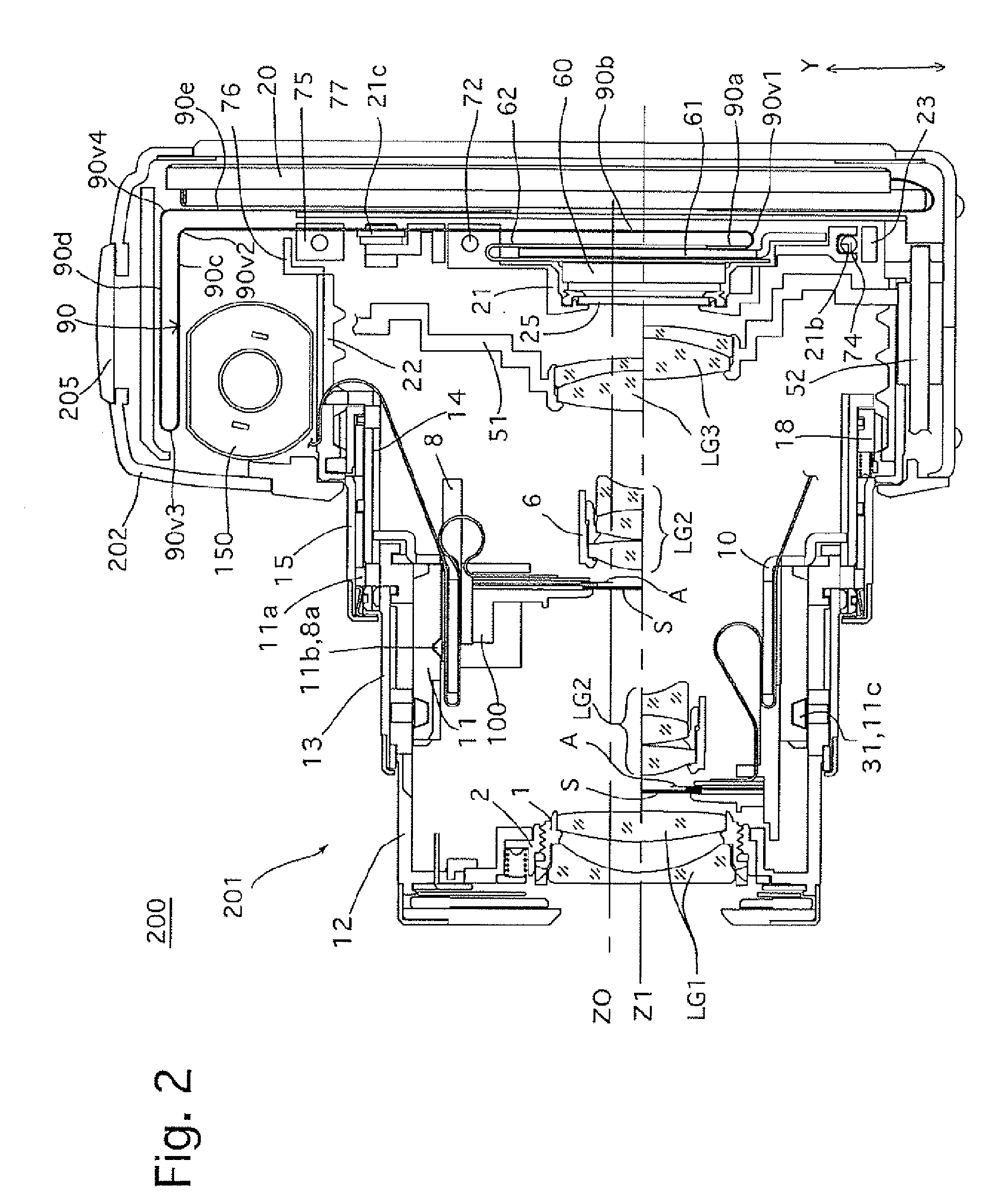
[0056]The zoom lens 201 of the digital camera 200, longitudinal sectional views of which are shown in FIGS. 2 and 3, is driven to advance toward the object side (leftward viewed in FIGS. 2 and 3) from the camera body 202 as shown in FIG. 2 during a photographing operation. When photography is not carried out, the digital camera 200 moves from a ready-to-photograph state shown in FIG. 2 to a fully-retracted state shown in FIG. 3 in which the zoom lens 201 is accommodated (fully retracted) in the camera body 202 as shown in FIG. 3. In FIG. 2, the upper half and the lower half of the zoom lens 201 from a...


PUM


Abstract

An optical apparatus including an electrical component which is movable in a plane, and a flexible printed wiring board in the shape of a strip, the widthwise direction thereof being parallel to the plane, which connects the electrical component to a stationary board, wherein the flexible printed wiring board includes a folded extension portion which firstly extends in a direction substantially orthogonal to the plane and is subsequently folded back at a folded portion to extend in a direction opposite thereto; and at least one slit which is provided to pass through the folded portion and to split at least a part of the folded extension portion into at least two split portions thereof in the widthwise direction of the flexible printed wiring board.

Description

BACKGROUND OF THE INVENTION[0001]1. Field of the Invention[0002]The present invention relates to an optical apparatus, more specifically relates to a structure of a flexible printed wiring board which is connected to a movable electrical component provided in an optical apparatus.[0003]2. Description of the Related Art[0004]A flexible printed wiring board is commonly used to electrically connect a movable electrical component to a stationary board such as a stationary circuit board. In many cases, a clearance is given to the length of the flexible printed wiring board in the direction of movement of the electrical component to reduce a resistance (or frictional resistance) in the flexible printed wiring board to movements of the electrical component by drawing or folding the flexible printed wiring board when the electrical component moves.[0005]However, if the motion of the electrical component is not a simple linear motion in one direction, e.g., if the electrical component is mov...

Claims


Application Information

Patent Timeline
Patent Type & Authority Patents(United States)
IPC IPC(8): H04N5/228G03B17/00H04N5/225
CPCG03B17/04H04N5/2253H05K1/028H04N5/23248G03B2217/005H05K2201/09063H05K1/189H05K2201/055H05K2201/052H05K2201/056H05K2201/10121H04N23/54H04N23/68
Inventor NOMURA, HIROSHIKOSAKO, KOSEISUZUKA, SHINYAINAZUKA, MASAHIROENDO, KEN
Owner HOYA CORP
Learn More