
Communication network optimization tool

a technology of communication network and optimization tool, which is applied in the field of digital radio frequency links, can solve the problems of difficult to model with great accuracy, model is unable to account for many situations, and miscalculation of rf link propagation loss,

Inactive Publication Date: 2009-09-08
US SEC THE ARMY THE
View PDF10 Cites 68 Cited by
  • Summary
  • Abstract
  • Description
  • Claims
  • Application Information

AI Technical Summary

Benefits of technology

[0013]In accordance with an embodiment of the present invention, a method for converging on a route through a radio frequency (RF) communications network, that comprises multiple nodes, comprises (a) identifying all RF links between each node in the RF communications network; (b) determining a connectivity confidence interval for each RF link by: (aa) developing a calculated signal to noise ratio using a radio frequency communication link propagation loss model; (bb) determining a threshold signal to noise ratio based on a predetermined RF packet completion rate; (cc) determining a standard deviation value based on a signal strength and a noise level at a signal receiving node; (dd) calculating a Z number, associated with a normal distribution table which is based on the threshold signal to noise ratio minus the calculated signal to noise ratio with that result being divided by the standard deviation value; and (ee) assigning a CCI probability value based on said Z number. The method further comprises (c) setting a predetermined connectivity confidence interval minimum; (d) comparing each connectivity confidence interval for each RF link to the predetermined connectivity confidence interval minimum to determine which are greater than or equal to the predetermined connectivity confidence interval; (e) assembling each RF link corresponding to each connectivity confidence interval that is greater than or equal to the predetermined connectivity confidence interval together to identify various routes through the RF network; (f) calculating a resultant connectivity confidence interval for each route by multiplying together each connectivity confidence interval for each RF link of each particular route; and (g) comparing each resultant connectivity confidence interval to identify the route with the greatest resultant connectivity confidence interval.

Problems solved by technology

While the signal models work quite well under a number of scenarios, the nature of the problem is such that the models are unable to account for many situations that can and do occur on the battlefield.
In the case of a communications system such as EPLRS, the RF noise background and RF propagation loss are two parameters that are difficult to model with great accuracy.
However, TIREM is static and does not adequately account for changes in RF signal and noise conditions, resulting in the miscalculation of RF link propagation losses.
While one could attempt to refine the model in order to account for various propagation conditions, the possible combinations are simply too numerous.
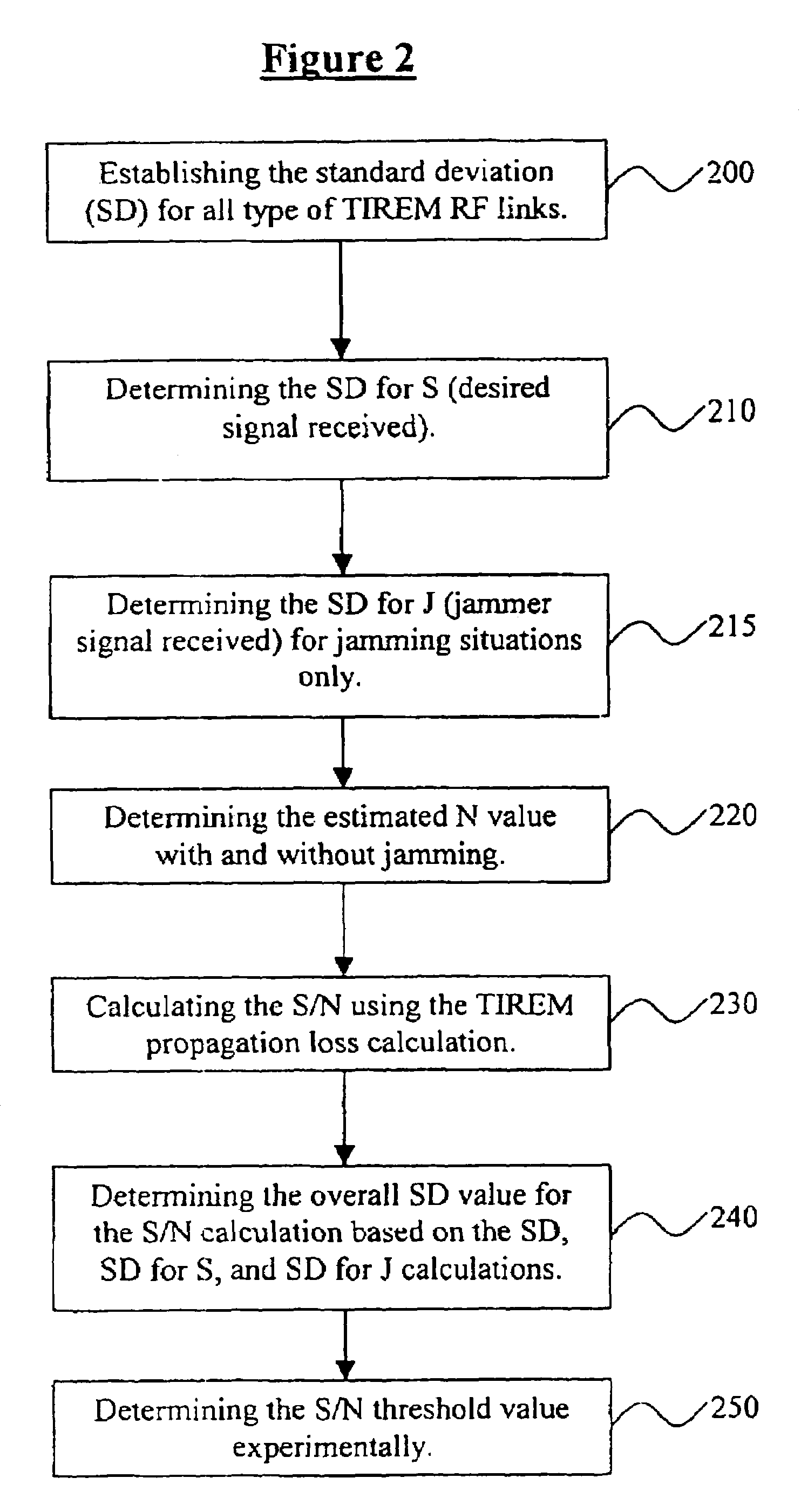
However, the S / N value calculated from the TIREM's nominal propagation loss value does not account for the standard deviation associated with the TIREM calculated propagation loss and actual measured values of propagation loss.

Method used


Image

  • Communication network optimization tool
  • Communication network optimization tool
  • Communication network optimization tool

Examples


Embodiment Construction

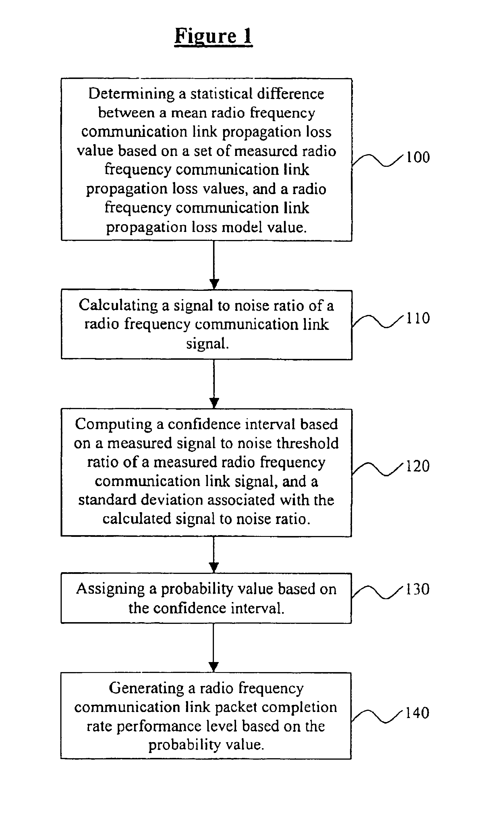
[0020]As previously mentioned, there is a need for an improved RFLPT process, which includes all digital packet structures transmitted over RF links and which overcomes the limitations of the conventional processes and systems. Referring now to the drawings, and more particularly to FIGS. 1 through 5, there are shown preferred embodiments of the invention.

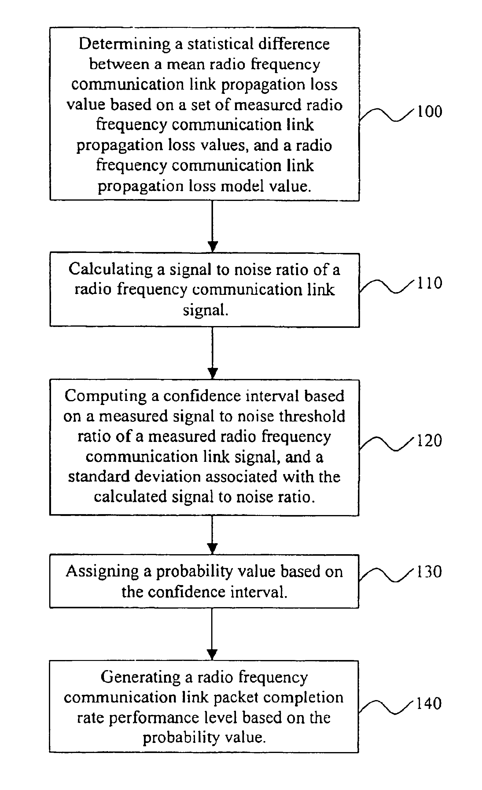
[0021]According to FIG. 1, a method for optimizing transmission of radio frequency communication link signals in a radio frequency communications network comprises determining 100 a statistical difference between a mean radio frequency communication link propagation loss value based on a set of measured radio frequency communication link propagation loss values, and a radio frequency communication link propagation loss model value. The next step involves calculating 110 a signal to noise ratio of a radio frequency communication link signal. Upon completion of this step, the process involves computing 120 a confidence interval based...


PUM


Abstract

A method for converging on a route through a radio frequency (RF) communications network, that includes multiple nodes, includes (a) identifying all RF links between each node in the RF communications network; (b) determining a connectivity confidence interval for each RF link by: (aa) developing a calculated signal to noise ratio using a radio frequency communication link propagation loss model; (bb) determining a threshold signal to noise ratio based on a predetermined RF packet completion rate; (cc) determining a standard deviation value based on a signal strength and a noise level at a signal receiving node; (dd) calculating a Z number, associated with a normal distribution table which is based on the threshold signal to noise ratio minus the calculated signal to noise ratio with that result being divided by the standard deviation value; and (ee) assigning a CCI probability value based on said Z number. The method further comprises (c) setting a predetermined connectivity confidence interval minimum; (d) comparing each connectivity confidence interval for each RF link to the predetermined connectivity confidence interval minimum to determine which are greater than or equal to the predetermined connectivity confidence interval; (e) assembling each RF link corresponding to each connectivity confidence interval that is greater than or equal to the predetermined connectivity confidence interval together to identify various routes through the RF network; (f) calculating a resultant connectivity confidence interval for each route by multiplying together each connectivity confidence interval for each RF link of each particular route; and (g) comparing each resultant connectivity confidence interval to identify the route with the greatest resultant connectivity confidence interval. An apparatus for carrying out such a method is also presented.

Description

GOVERNMENT INTEREST[0001]The invention described herein may be manufactured, used, imported, sold, and licensed by or for the Government of the United States of America without the payment of any royalty thereon or there for.BACKGROUND OF THE INVENTION[0002]1. Field of the Invention[0003]The present invention generally relates to digital radio frequency (RF) links, and more particularly to a radio frequency link performance tool (RFLPT) process and system, which predicts the successful transmission of digital packets over an RF link with RF interference, such as jamming or Electronic Warfare (EW) effects, and without an intentional interference (non-jamming) environment.[0004]2. Related Art[0005]A method for optimizing an RF communications network for use in a battlefield environment is described in U.S. Pat. No. 6,232,909 issued to Masciulli, the complete disclosure of which is herein incorporated by reference (hereinafter referred to as “the '909 patent”). The '909 patent describe...

Claims


Application Information

Patent Timeline
Patent Type & Authority Patents(United States)
IPC IPC(8): H04B7/208G01S7/42H04B15/00
CPCH04L45/122H04W40/12H04L45/124Y02D30/70
Inventor MASCIULLI, MICHAEL
Owner US SEC THE ARMY THE
Learn More