Windshield wiper

a technology of windshield wiper and wiper body, which is applied in the field of windshield wiper, can solve the problems of wasting manual work, inconvenient and complicating manufacturing process, and achieves the effects of saving manual work, simplifying manufacturing process, and facilitating assembly of windshield wiper

Inactive Publication Date: 2009-09-15
LIN CHIN LIEN
View PDF8 Cites 77 Cited by
  • Summary
  • Abstract
  • Description
  • Claims
  • Application Information

AI Technical Summary

Benefits of technology

[0008]The primary objective of the present invention is to provide a windshield wiper having a simplified manufacturing process without needing riveting and bonding actions.
[0009]Another objective of the present invention is to provide a windshield wiper, wherein each of the two elastic plates is snapped into the respective snapping plate of the connecting seat so that each of the two elastic plates is mounted in the connecting seat in a snapping manner without needing the riveting process, thereby greatly facilitating assembly of the windshield wiper and saving the manual work.
[0010]A further objective of the present invention is to provide a windshield wiper, wherein each of the two side covers has two locking posts each inserted into and locked in the locking hole of each of the two elastic plates so that each of the two side covers is mounted on the two elastic plates closely without needing an adhesive, thereby simplifying the manufacturing process, and enhancing the productivity of the windshield wiper.
[0011]A further objective of the present invention is to provide a windshield wiper, wherein each of the two side covers is positioned on the two elastic plates exactly, thereby preventing each of the two side covers from being detached from the two elastic plates during a long-term utilization.
[0012]A further objective of the present invention is to provide a windshield wiper, wherein the shelter is mounted around the periphery the connecting seat to enhance the aesthetic quality of the windshield wiper.

Problems solved by technology

However, the articulation 12 is secured to the steel plate 11 by riveting, so that it is difficult to mount the articulation 12 on the steel plate 11, thereby causing inconvenience in assembly of the windshield wiper and wasting the manual work.
In addition, each of the two side covers 14 is bonded on the respective protective hood 13 by an adhesive, thereby complicating the manufacturing process, and decreasing the productivity of the windshield wiper.
Further, the articulation 12 is directly exposed outward from the steel plate 11, thereby decreasing the aesthetic quality of the windshield wiper.

Method used


Image

  • Windshield wiper
  • Windshield wiper
  • Windshield wiper

Examples


Embodiment Construction

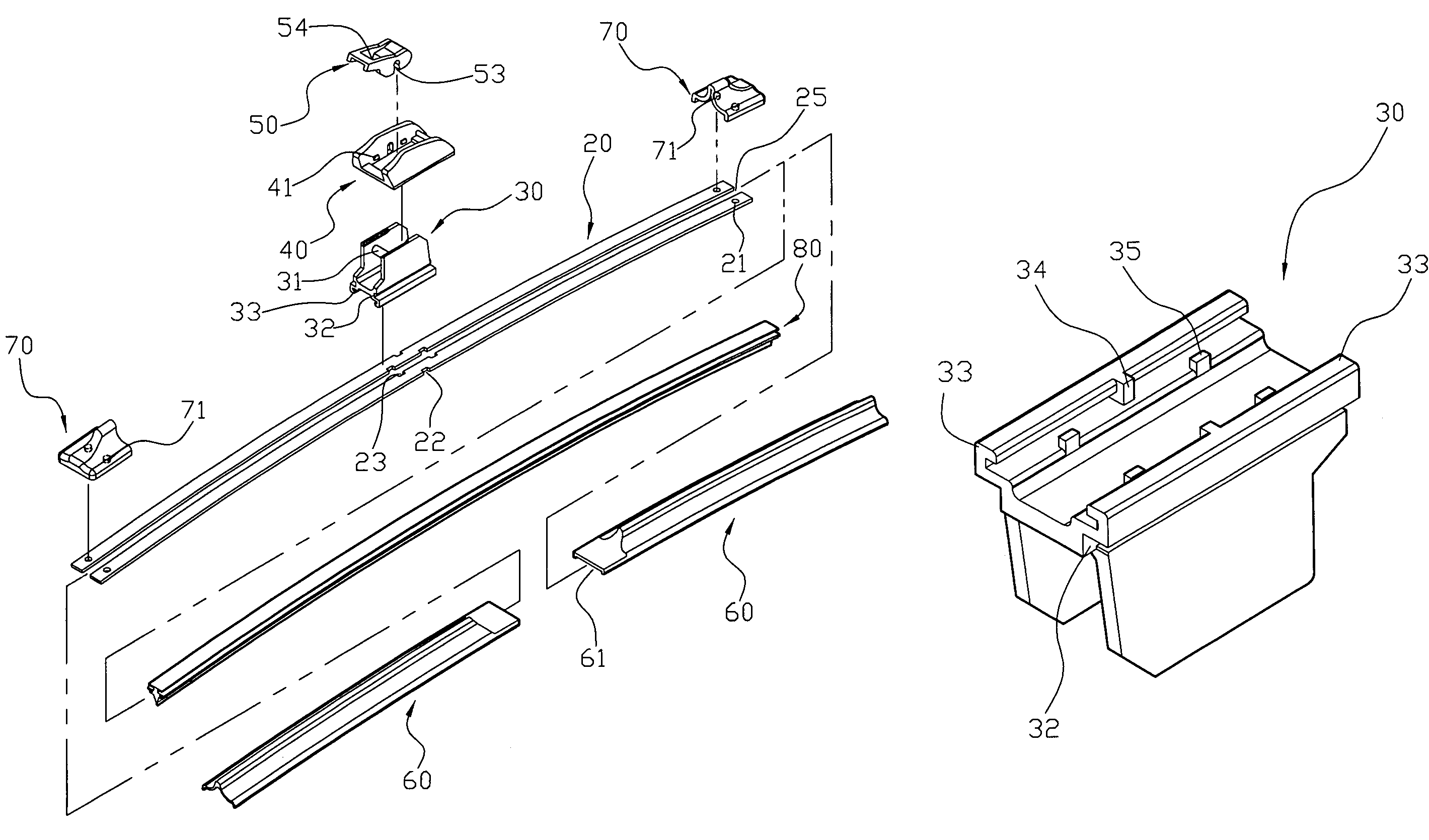
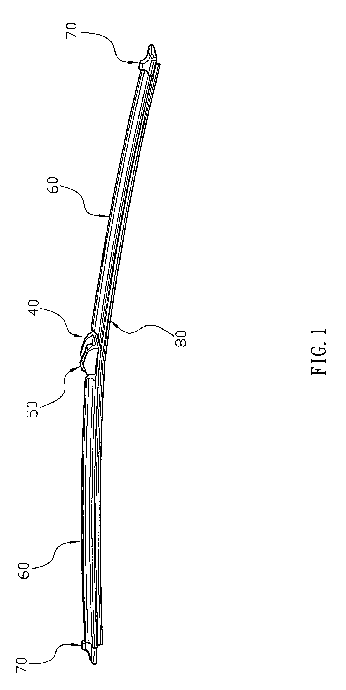
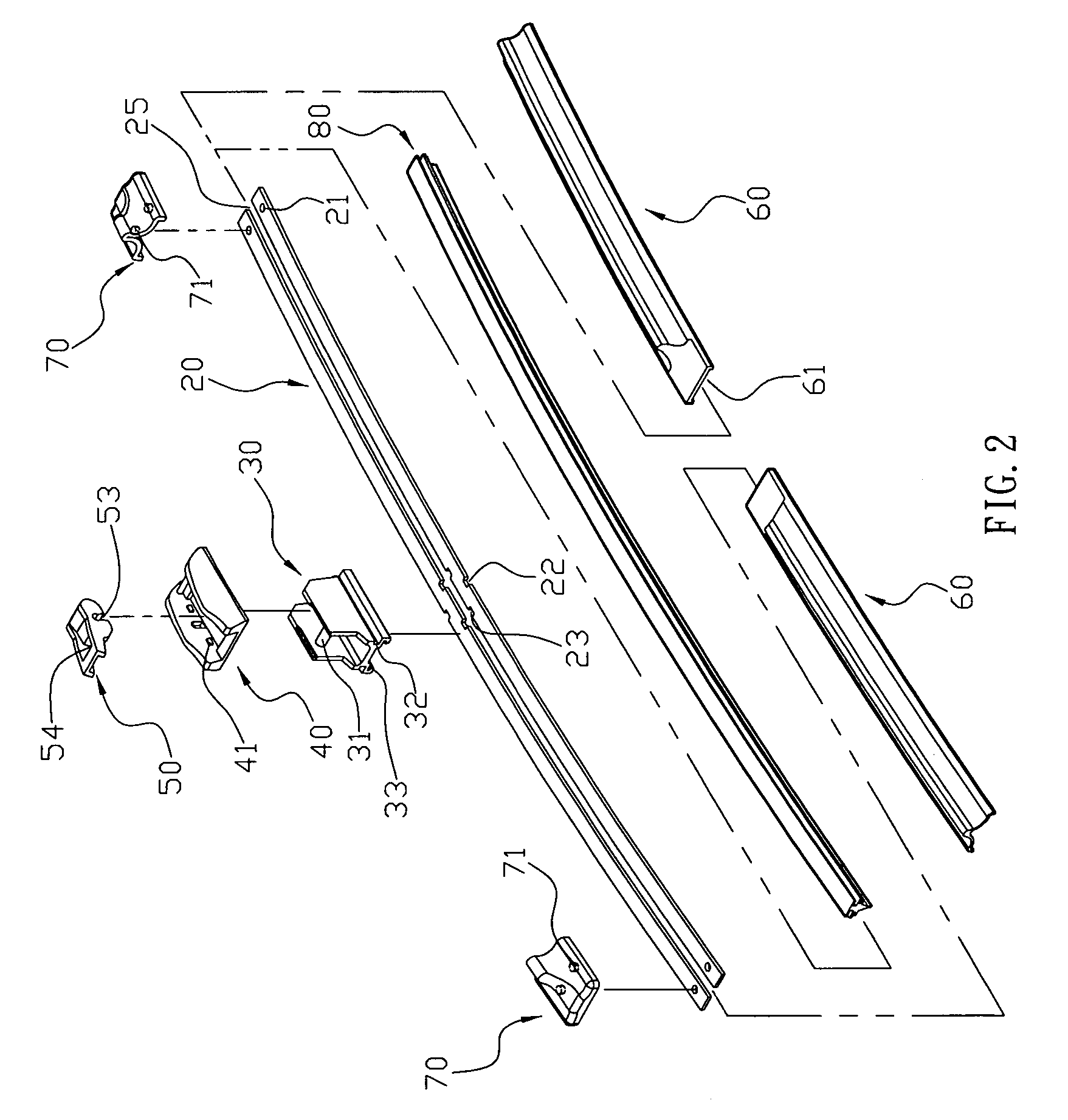
[0023]Referring to the drawings and initially to FIGS. 1 and 2, a windshield wiper in accordance with the preferred embodiment of the present invention comprises a connecting seat 30, two elastic plates 20, a wiper 80, two rubber protective hoods 60, two side covers 70, a shelter 40, and a connecting block 50.

[0024]Referring to FIGS. 1-7, the connecting seat 30 has a lower portion having two sides each formed with a snapping plate 33 and a hollow upper portion provided with a pivot shaft 31. The connecting seat 30 has a periphery formed with two locking grooves 32 each located above the respective snapping plate 33. The snapping plate 33 of the connecting seat 30 is substantially inverted L-shaped and has an inner side having a mediate portion formed with a locking block 34. The connecting seat 30 has a bottom having two sides each formed with at least one insertion block 35 (preferably two insertion blocks 35) spaced from the locking block 34.

[0025]Each of the two elastic plates 20...


PUM


Abstract

A windshield wiper includes a connecting seat, two elastic plates, a wiper, two rubber protective hoods, two side covers, a shelter, and a connecting block. Thus, each of the elastic plates is snapped into the respective snapping plate of the connecting seat so that each of the elastic plates is mounted in the connecting seat in a snapping manner without needing the riveting process. In addition, each of the side covers has two locking posts each locked in the locking hole of each of the elastic plates so that each of the side covers is mounted on the elastic plates closely without needing an adhesive.

Description

BACKGROUND OF THE INVENTION[0001]1. Field of the Invention[0002]The present invention relates to a windshield wiper, and more particularly to a windshield wiper having a simplified manufacturing process without needing riveting and bonding actions.[0003]2. Description of the Related Art[0004]A conventional windshield wiper 10 in accordance with the prior art shown in FIGS. 8 and 9 comprises a steel plate 11 including an axially extended fixing slot 111 having an end formed with an enlarged opening 112, a wiper 15 mounted in the fixing slot 111 of the steel plate 11, two protective hoods 13 each mounted on one of two ends of the steel plate 11 and having a mounting hole 131 mounted on the steel plate 11, two side covers 14 each mounted on the respective end of the steel plate 11 and each rested on the respective protective hood 13, and an articulation 12 mounted on the steel plate 11 and located between the two protective hoods 13. The steel plate 11 has a mediate portion formed with...

Claims


Application Information

Patent Timeline
Patent Type & Authority Patents(United States)
IPC IPC(8): B60S1/38B60S1/40
CPCB60S1/3858B60S1/3879B60S1/3889
Inventor LIN, CHIN-LIEN
Owner LIN CHIN LIEN
Why Eureka
Try Eureka