Dispensing unit

a technology of dispensing unit and dispensing chamber, which is applied in the direction of liquid transfer device, liquid handling, packaging goods type, etc., can solve the problems of logistical drawbacks, achieve accurate quantity, and reduce the volume of the reservoir

Inactive Publication Date: 2009-09-15
AIRSPRAY INT
View PDF16 Cites 6 Cited by
  • Summary
  • Abstract
  • Description
  • Claims
  • Application Information

AI Technical Summary

Benefits of technology

[0043]It is preferable for the first and second reservoirs to be of the “airless” type, i.e. for the fluid substance dispensed not to be replaced in the reservoir by air, but rather for the volume of the reservoir to be reduced as the volume of the fluid substance dispensed increases. This is possible, for example, by designing the reservoir as a flexible pouch which becomes smaller as the fluid substance is dispensed. The “airless” reservoir is pr...

Problems solved by technology

This leads to logistical drawbacks relating to the storage and production of thes...

Method used


Image

  • Dispensing unit
  • Dispensing unit
  • Dispensing unit

Examples


Embodiment Construction

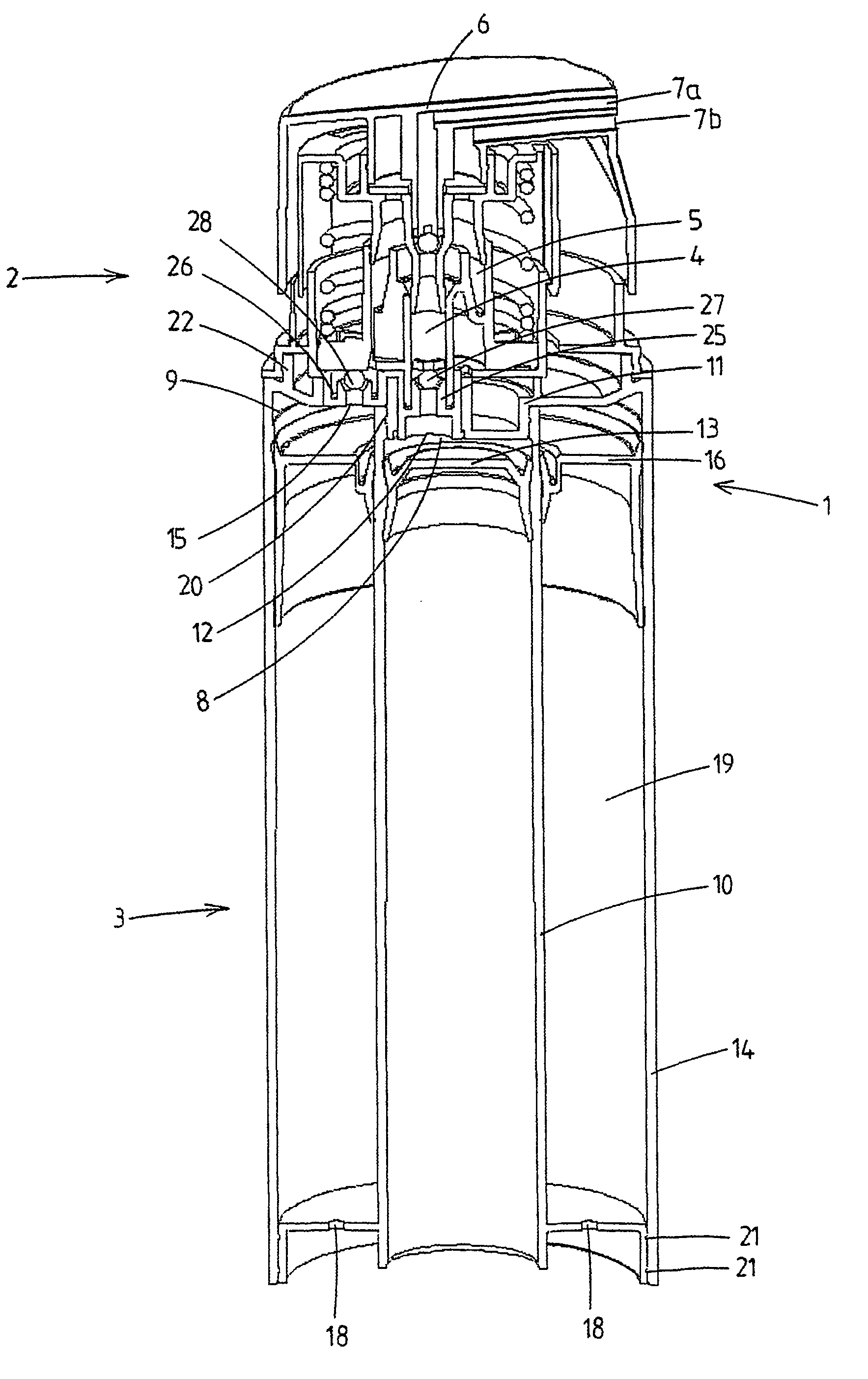
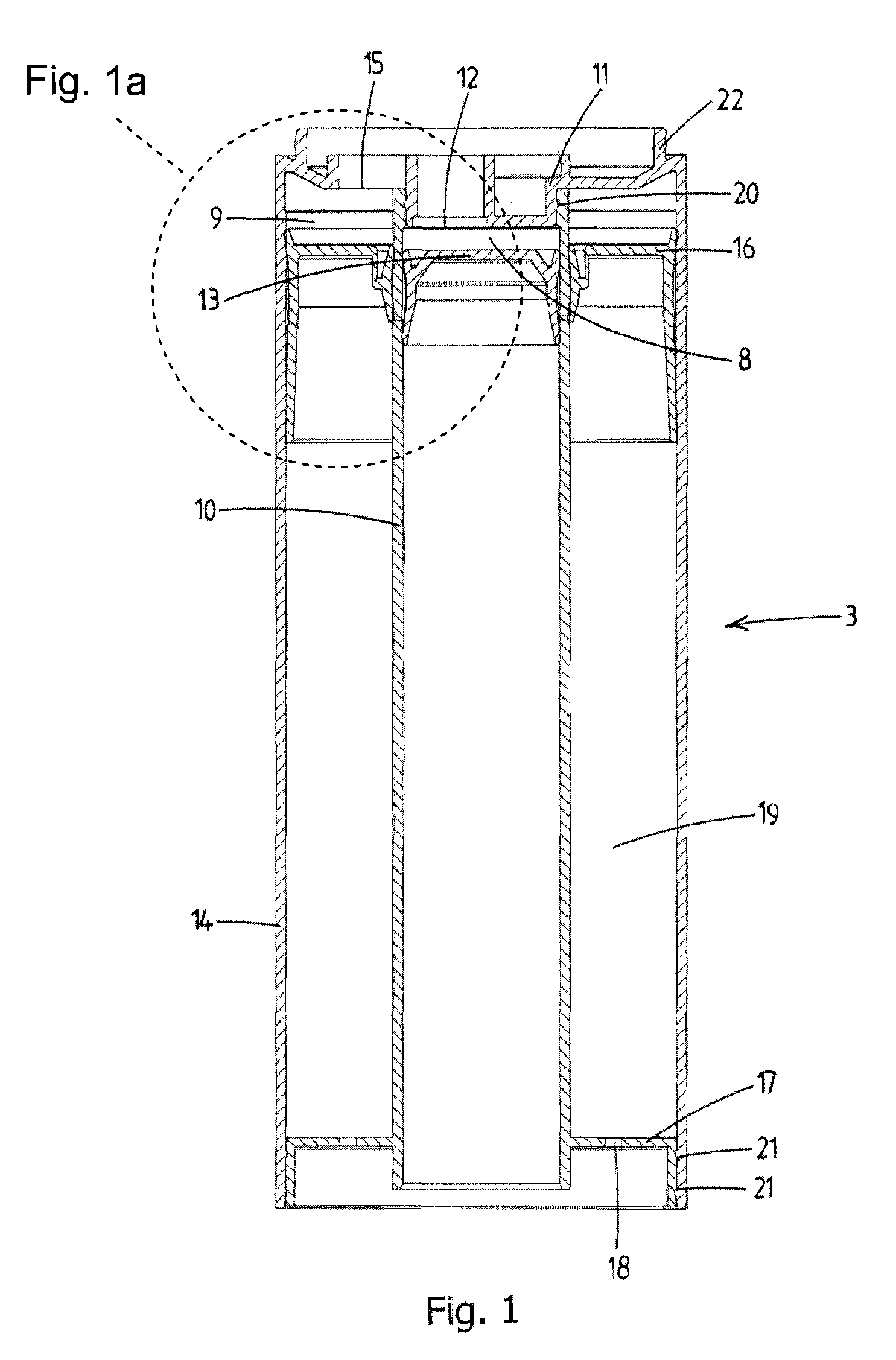
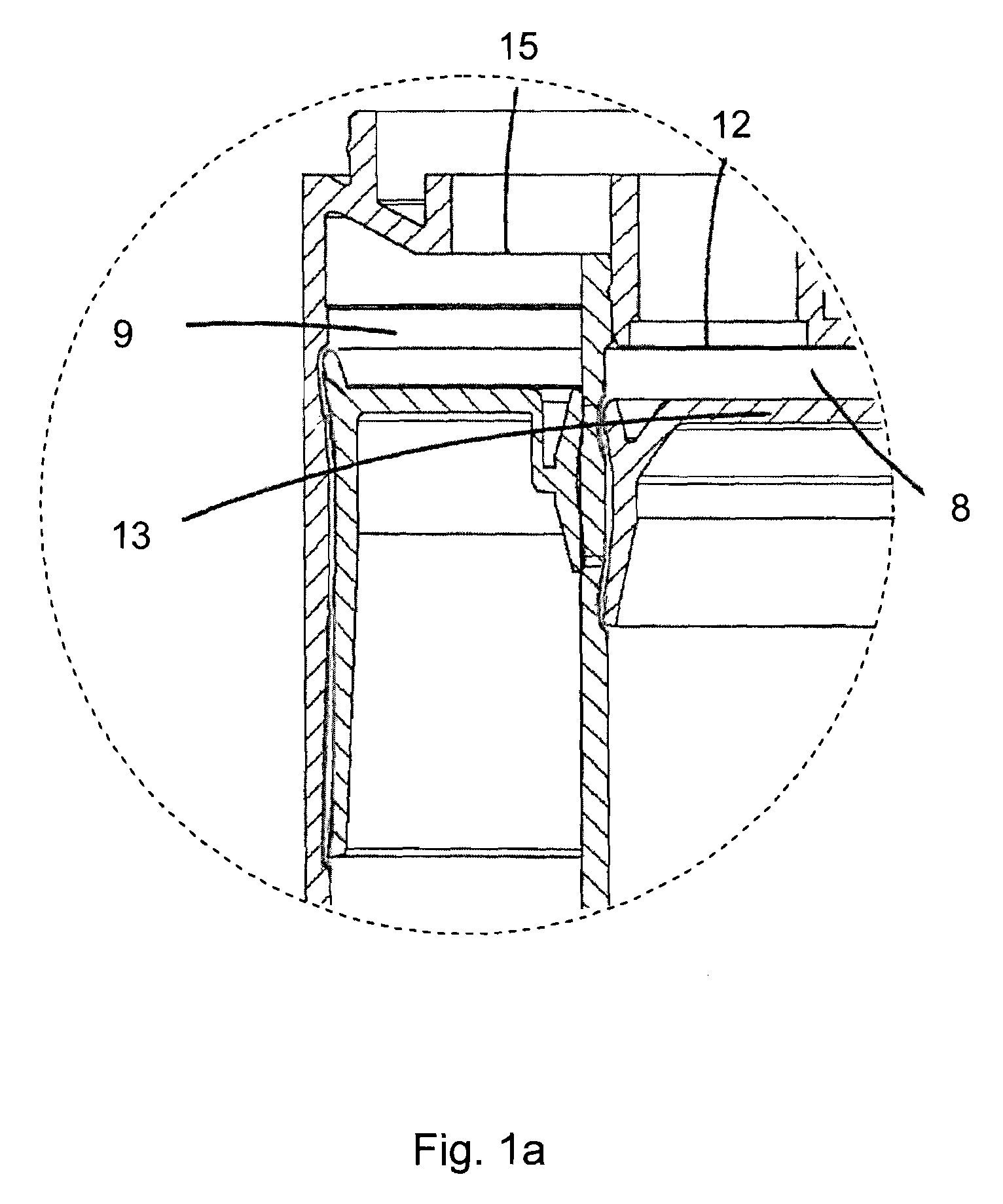
[0056]FIG. 2 shows a dispensing unit for simultaneously dispensing two fluid substances, denoted overall by reference numeral 1. The dispensing unit 1 is suitable for holding in the hand and comprises a pump assembly 2 and a reservoir assembly 3. The pump assembly 2 and the reservoir assembly 3 are assemblies which are separate but can be coupled to one another and in this figure are shown coupled to one another. The reservoir assembly 3 is shown separately in FIG. 1.

[0057]The pump assembly 2 of the dispensing unit 1 comprises a first pump 4 and a second pump 5, and also an operating member which is designed as an operating button 6. By operation of the operating button 6, the first and second pumps 4, 5 are actuated, with the fluid substances being dispensed simultaneously through dispensing openings 7a, 7b. The pumps 4, 5 shown are piston pumps. It is also possible to provide pumps of a different type, for example bellows pumps, instead of piston pumps.

[0058]If appropriate, the pu...


PUM

PropertyMeasurementUnit
Diameteraaaaaaaaaa
Lengthaaaaaaaaaa
Widthaaaaaaaaaa

Abstract

The invention relates to a dispensing unit for dispensing two fluid substances. The dispensing unit comprises a pump assembly (2) having a first (4) and a second pump (5) which can be actuated by common, manually operable operating means (6) in order to simultaneously dispense the two fluid substances. The dispensing unit also comprises a reservoir assembly (3), the reservoir assembly comprising two reservoirs which are each provided at an outlet side with an outlet and are each delimited by a movable piston (13, 16) on the other side from the outlet, which pistons, during the dispensing of the fluid substances, move toward the respective outlets. According to a first aspect of the invention, the reservoir assembly (3) and the pump assembly (2) are separate assemblies which can be coupled to one another, in such a manner that in the uncoupled state each reservoir can be filled through the outlet of the reservoir, after which the pump assembly and the reservoir assembly are coupled to one another.

Description

CROSS-REFERENCE TO RELATED APPLICATIONS[0001]This application is the National Stage of International Application No. PCT / NL03 / 00489, filed Jun. 18, 2003, which claims the benefit of Netherlands Application No. NL 1020889, filed Jun. 18, 2002 and Netherlands Application No. NL 1020890, filed Jun. 18, 2002, the contents of each of which are incorporated by reference herein.FIELD OF THE INVENTION (I)[0002]A first aspect of the present invention relates to a dispensing unit for dispensing two fluid substances in accordance with the preamble of originally filed claim 1. The first aspect of the invention also relates to the reservoir assembly of a dispensing unit of this type.BACKGROUND OF THE INVENTION (I)[0003]WO 93 / 04940 has disclosed a dispensing device for simultaneously dispensing two fluid substances.[0004]This dispensing device has a first reservoir, which is delimited by an inner side of a first cylindrical tube, and a second reservoir, which is delimited by the outer side of the...

Claims


Application Information

Patent Timeline
IPC IPC(8): B67D5/52B67D7/70B05B11/00
CPCB05B11/0048B05B11/3085B05B11/3047B05B11/0097B05B11/028B05B11/1047B05B11/1085
Inventor VAN DER HEIJDEN, EDGAR IVO MARIA
Owner AIRSPRAY INT
Why Eureka
Try Eureka