Optical apparatus

a technology of optical equipment and optical arc, which is applied in the direction of fixed installation, lighting and heating equipment, instruments, etc., can solve the problem of blocking the radiation of the discharge arc (lb>1/b>)

Inactive Publication Date: 2009-09-15
USHIO DENKI KK
View PDF11 Cites 1 Cited by
  • Summary
  • Abstract
  • Description
  • Claims
  • Application Information

AI Technical Summary

Benefits of technology

[0027]In this invention, the concave reflecting mirror comprises a front elliptical reflecting mirror portion, a middle spherical reflecting mirror portion, and a rear elliptical reflecting mirror portion, and so light reflected by the rear elliptical reflecting mirror portion does not return to the discharge arc, but is reflected toward the front opening.
[0028]Moreover, the relationship between the angle α formed by a virtual tangential line VTL, which runs from the center position A1 between the electrodes to the outer surface of the electrode positioned towards neck of the concave reflecting mirror, and the direction in which the electrode of the discharge lamp extends and the angle β formed by a virtual straight line VSL, which runs from the center position CP to the boundary position between the middle spherical reflecting mirror portion and the rear elliptical reflecting mirror portion, and the direction in which the electrode of the discharge lamp extends is β>α, and so the shape of the electrode positioned toward the neck is stipulated in such a way that the light to be reflected by the rear elliptical reflecting mirror portion will be adequate.
[0029]Moreover, because the relationship between the volume V (in mm3) of the one of the pair of discharge lamp electrodes that is positioned opposite the direction of light radiation of the concave reflecting mirror and the wattage (P) during steady lighting meets the condition, 0.07×EXP(0.014×P)<V, the function of withstanding heat capacity can be preserved while meeting the stipulation of the size and shape of the electrode positioned toward the neck.

Problems solved by technology

In the event that the volume of the electrode is enlarged, however, there is still the problem that the light radiated by the discharge arc (L1) is blocked by the body of the electrode, or the light reflected by the reflecting mirror 200 is blocked by the electrodes or other constituent parts of the lamp.

Method used


Image

  • Optical apparatus
  • Optical apparatus
  • Optical apparatus

Examples


Embodiment Construction

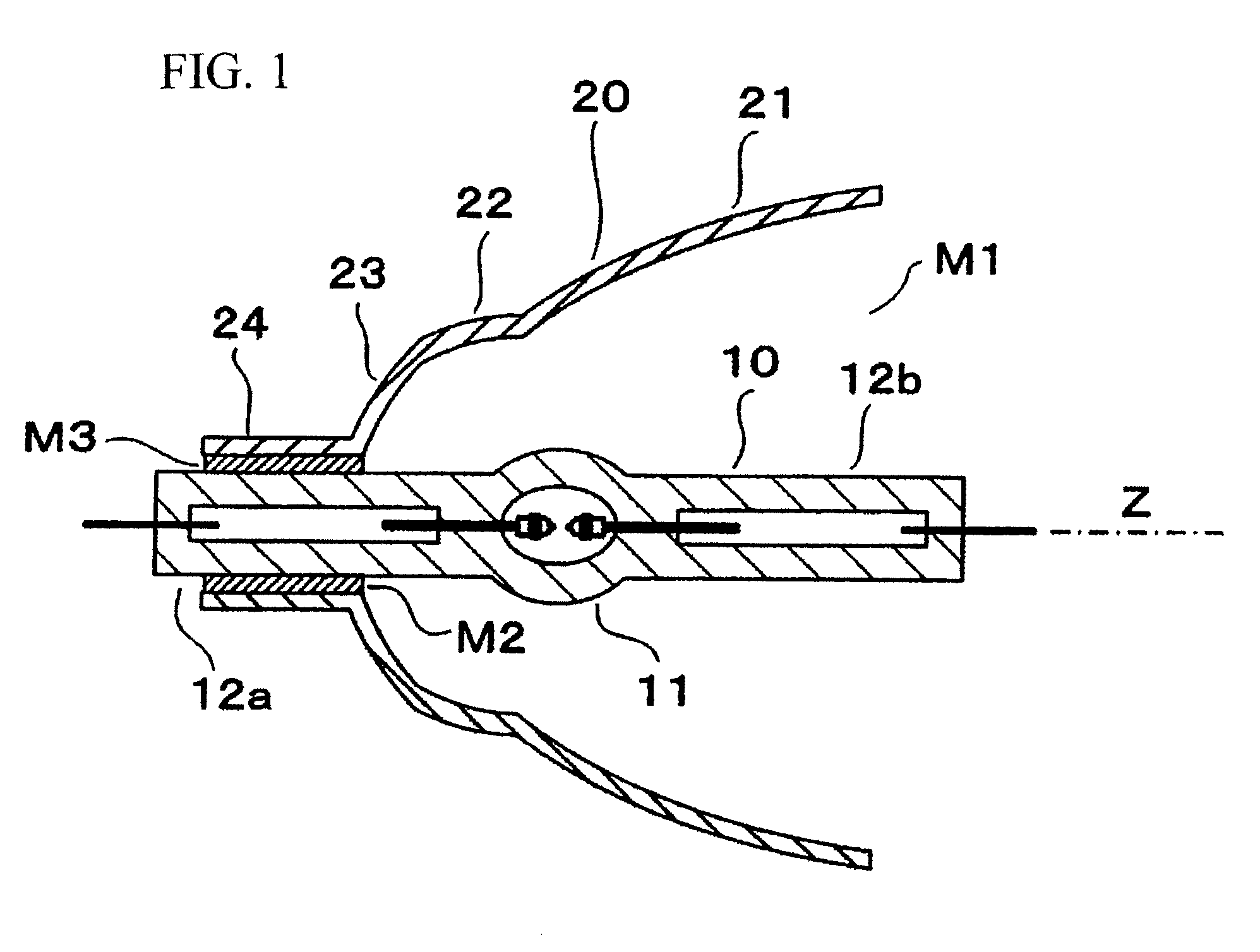
[0040]FIG. 1 shows the overall structure of the optical apparatus of this invention.

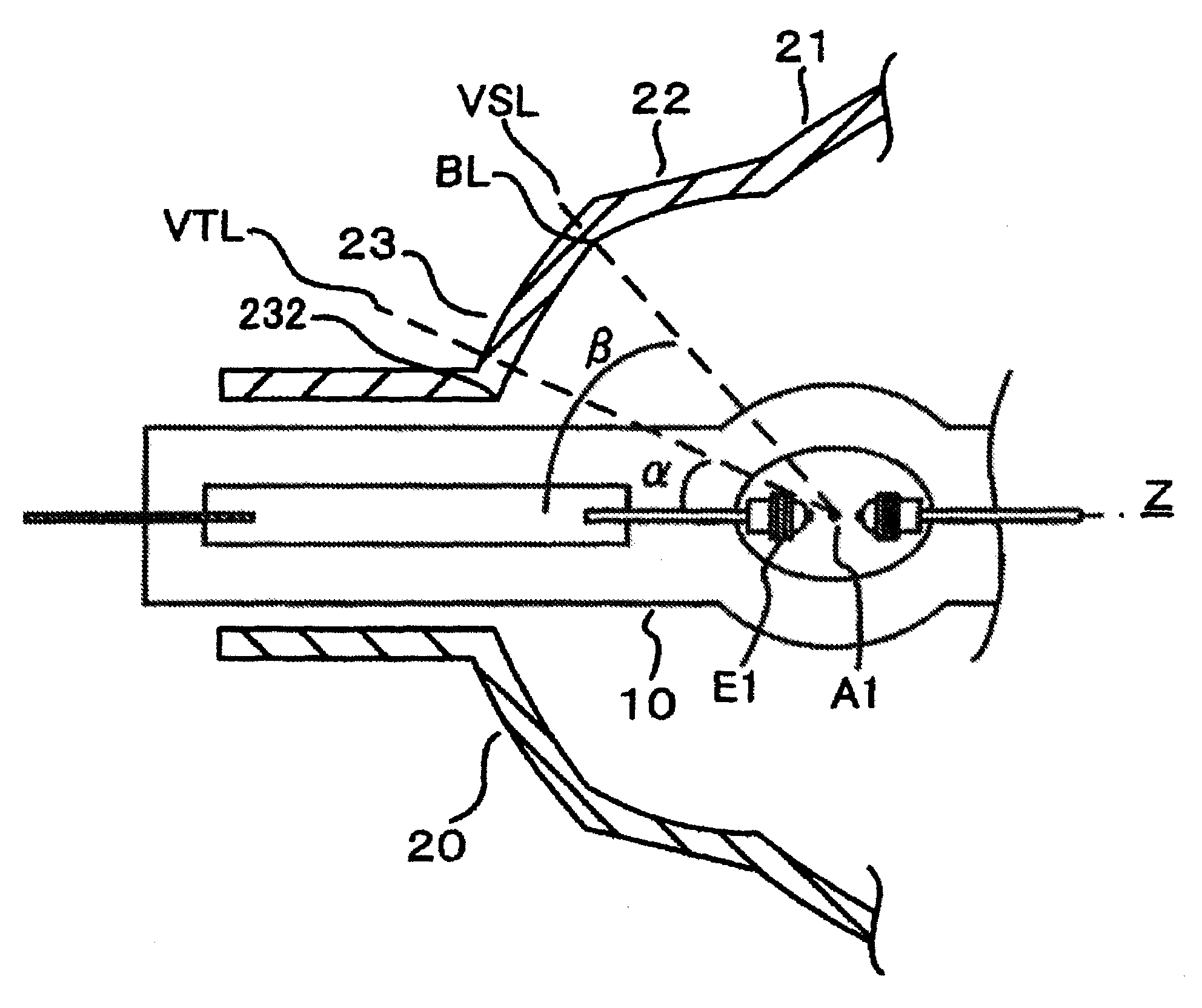
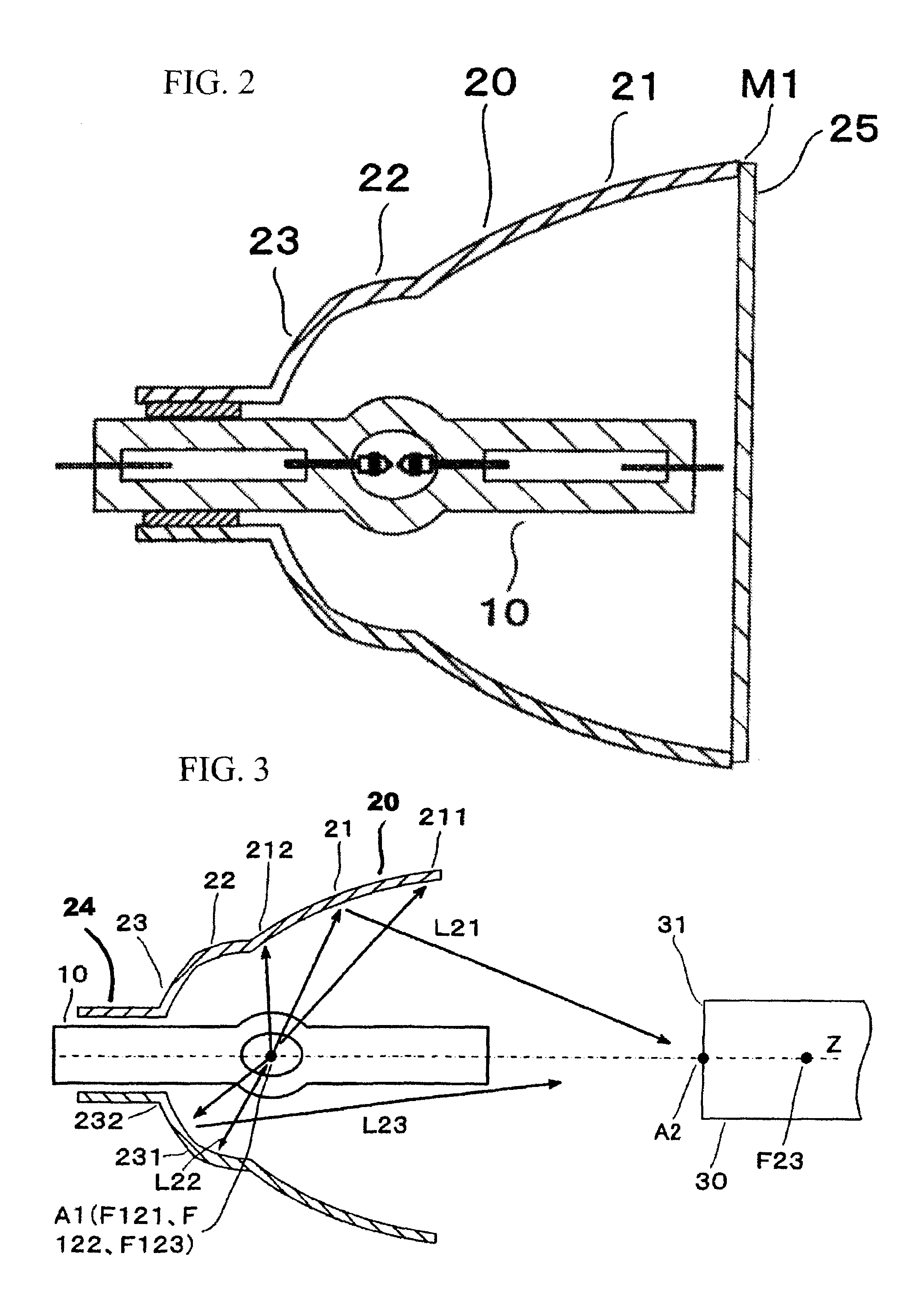
[0041]The optical apparatus comprises a discharge lamp (simply called a “lamp” hereafter) 10 and a concave reflecting mirror (simply called a “reflecting mirror” hereafter) 20. The lamp 10 has a pair of electrodes facing each other within the light-emitting portion. The reflecting mirror 20 is placed to surround the lamp 10, and the beam axis Z of the reflecting mirror 20 matches the direction of the arc of the lamp 10, or in other words, the direction of a line connecting the tips of the electrodes.

[0042]The lamp 10 has a light-emitting portion 11 with hermetically sealed portions 12 (12a, 12b) at both ends, and one of the hermetically sealed portions 12a is installed in the neck 24 of the reflecting mirror 20. An adhesive or other means is used to fix the lamp 10 and the reflecting mirror 20, but it is acceptable to install both directly as in the figure, or to use a separate fitting (reflector bas...


PUM


Abstract

Optical apparatus with a discharge lamp and a concave reflecting mirror, the concave reflecting mirror has a front elliptical reflecting mirror portion, a middle spherical reflecting mirror portion, and a rear elliptical reflecting mirror portion; the relationship between an angle α between a virtual tangential line VTL, which runs from the center position between the electrodes to the outer surface of the electrode positioned towards the neck of the concave reflecting mirror, and the beam axis Z and an angle β between a virtual straight line VSL, which runs from the center position between the electrodes to the boundary position between the middle spherical reflecting mirror portion and the rear elliptical reflecting mirror portion, and the beam axis Z is β>α; and the relationship between the volume V of the electrode E1 (mm3) and the wattage (P) meets the condition, 0.07×EXP(0.014×P)<V.

Description

BACKGROUND OF THE INVENTION[0001]1. Field of Invention[0002]This invention concerns an optical apparatus. In particular, it concerns an optical apparatus used in projection equipment.[0003]2. Description of Related Art[0004]Projection equipment is generally either the type that uses liquid crystal (LCD) panels or the type that uses DLP.[0005]The type that uses liquid crystal panels has both a one-layer variety and a three-layer variety, but with either variety, the beam emitted from the light source is split into three colors (RGB—R=red, G=green, B=blue), and after transmission coordination of the light corresponding to image information in the liquid crystal panel, the three colors that pass through the panels are combined and projected onto a screen.[0006]In the type that uses DLP, on the other hand, the beam emitted from the light source passes through a rotating filter by which the RGB domains are divided and formed, irradiated by means of time division such as a space modulatio...

Claims


Application Information

Patent Timeline
Patent Type & Authority Patents(United States)
IPC IPC(8): F21V7/00
CPCF21V7/04F21V7/09H01J61/86G03B21/2026H01J61/0732G03B21/006
Inventor TOMA, TAKAHIROHORIKAWA, YOSHIHIROKONTANI, TORU
Owner USHIO DENKI KK
Why Eureka
Try Eureka