
Methods and apparatus for controlling wind turbines

a technology of wind turbines and control methods, applied in the direction of wind turbines, mechanical equipment, machines/engines, etc., can solve the problems of large gravitational load, complex aerodynamics, and large diameter of rotors, and achieve the effects of reducing load, improving balance, and selecting methods according

Active Publication Date: 2019-12-10
VESTAS WIND SYST AS
View PDF18 Cites 1 Cited by
  • Summary
  • Abstract
  • Description
  • Claims
  • Application Information

AI Technical Summary

Benefits of technology

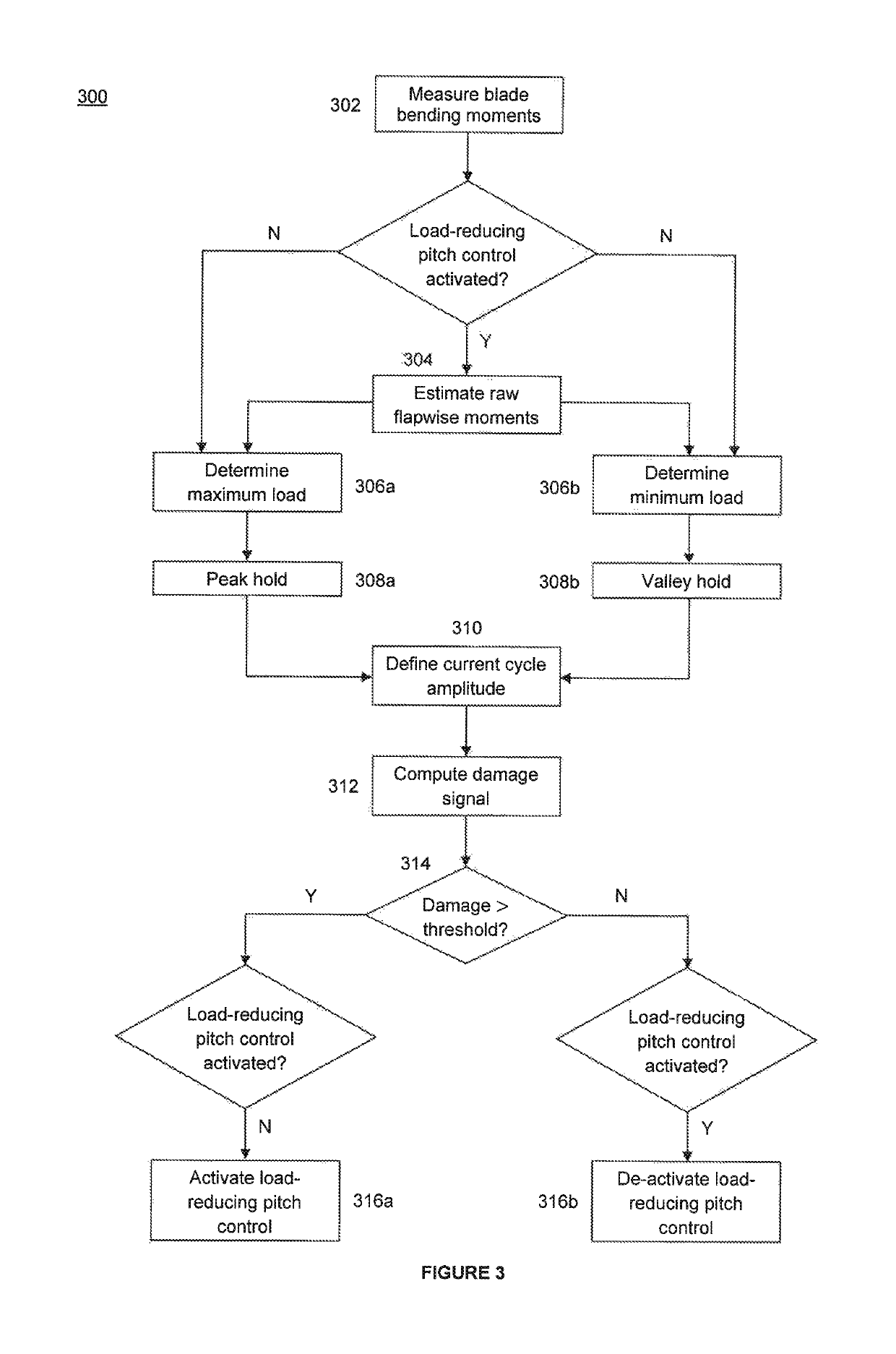
[0008]According to the present invention there is provided, in a first aspect, a method for controlling a wind turbine comprising the steps of determining an operational load on one or more wind turbine components; determining, based on the load, a damage signal that is indicative of the potential damage to the component(s); and applying a chosen load-reducing control strategy to the wind turbine whenever the damage signal exceeds a pre-defined threshold level in order to mitigate the foreseen damage.
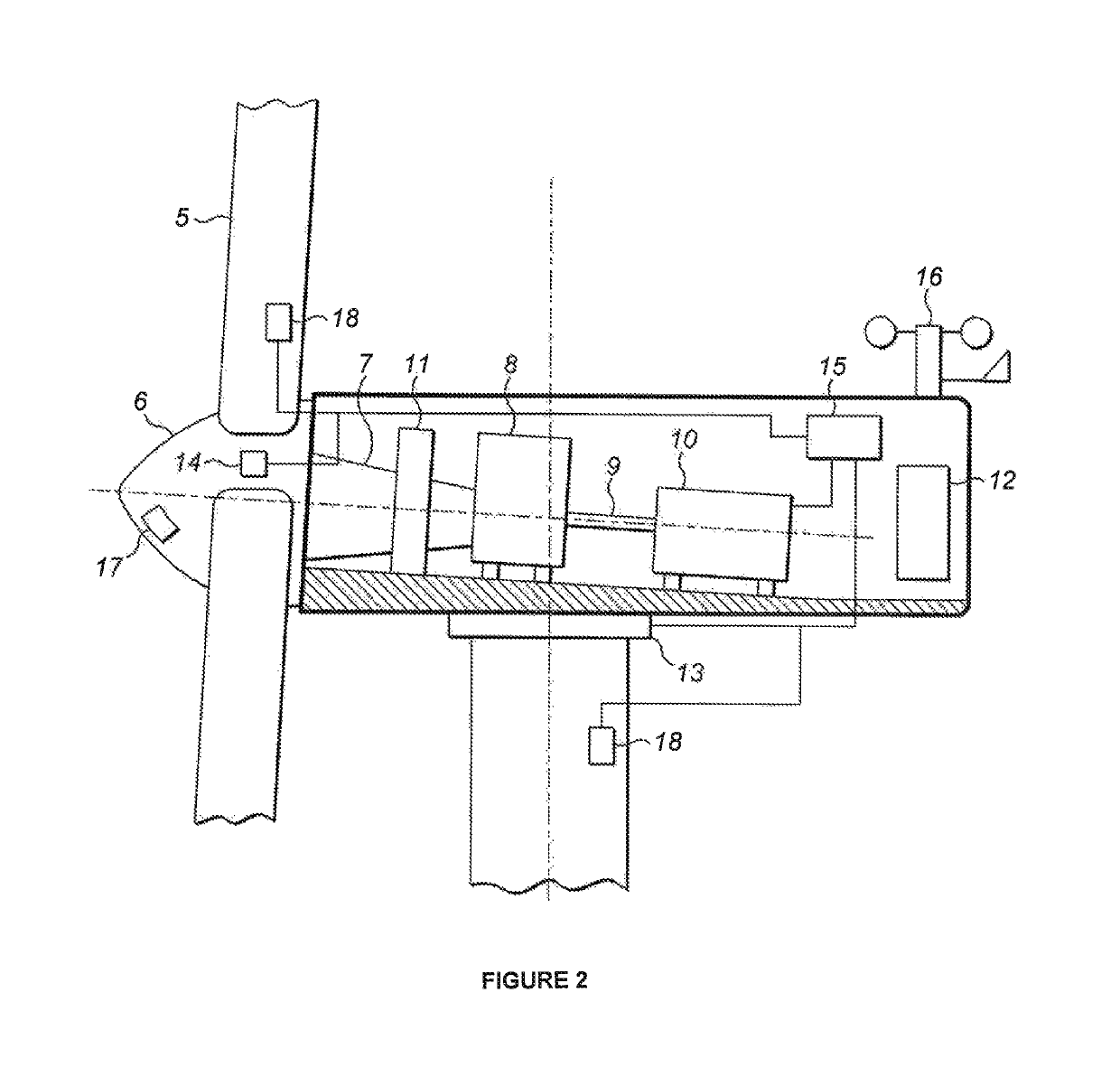
[0015]In a second aspect, the invention provides a control system for a wind turbine, the control system comprising a sensor for measuring a load on a wind turbine component and a controller for determining a damage signal based on the load and, wherein when the damage signal exceeds a pre-determined threshold level, the controller is operable to apply a control strategy to the wind turbine to mitigate potential damage to the component.
[0017]Embodiments of the invention have the advantage that a control measure for reducing a given load may be activated based on the predicted effects of the load on one or more specific components. By relating the decision to implement load-attenuating control directly to the degree of damage that a load may cause, a more calculated and farsighted approach to control activation may be realised. Consequently, unnecessary wear of control actuation mechanisms may be lessened, resulting in a reduction in undue, inevitably costly, maintenance.
[0019]The damage signal may be any measure of the damage or fatigue that a wind turbine component is sustaining or will sustain as a result of the determined load. In preferred embodiments of the invention, the measured or derived load may be used in the calculation of a damage signal that takes into account the mechanical properties of the component in question. In that case, the degree to which the damage signal reflects the wear of the loaded component or components to which it corresponds may be increased, such that the selectivity of methods according to these embodiments may advantageously be improved. Since comparatively smaller loads may lead to the activation of the appropriate control strategies, components that are more susceptible to damage can be prioritised. In an embodiment, the damage signal depends on the non-linear fatigue properties of the loaded wind turbine component. This may be implemented, for example, in a damage signal that is a function of the Wöhler exponent of the component. In other embodiments, signals representative of the established load itself may constitute an adequate reflection of the damage that the load brings about. In addition, lifetime usage estimators such as those described in WO 2013 / 044925 may be used to give a further reference signal that is an indication of the fatigue life already consumed by any wind turbine component or components of interest, i.e., of the accumulated damage already undergone. This may further improve the balance between the loading of the turbine components and the wear of control actuation mechanisms.
[0020]In some embodiments, measured loads may be used to modify not only the activation of a given control algorithm, but also one or more parameters used within the running of that algorithm. As an example, common control algorithms work by comparing one or more measured loads to corresponding reference values and adjusting the operating setpoints of the turbine in such a way as to reduce the loads towards these desired values. Currently, reference values are typically set either to zero or to a more or less arbitrary non-zero value. Increasing the reference away from zero has the advantage that the amount by which a load is to be decreased is effectively reduced, such that the degree of control action taken is ultimately regulated. As discussed in more detail below, methods according to the present invention may derive a non-zero reference value for a control algorithm from the current loads on one or more wind turbine components. The reference value so determined may advantageously be less arbitrary than those used in existing methods and may furthermore be varied over time in such a way as to mirror the loading experienced by the turbine.

Problems solved by technology

Of increasing concern, however, are on the other hand the manifold loads that various turbine components may sustain, especially when operating in more turbulent conditions.
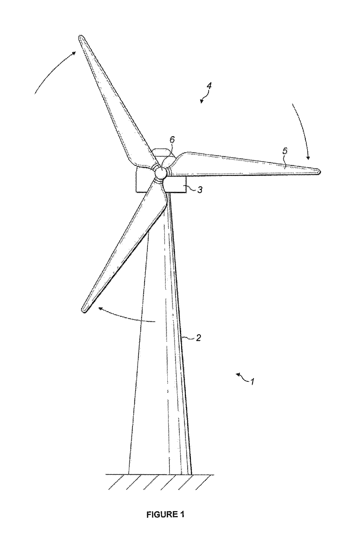
This is especially so in the case of very large turbines, the height and rotor diameter of which give rise to considerable gravitational loading as well as to complex aerodynamic interactions with the incoming wind field.
Some loads, such as the gravitational force acting on the structure as a whole, are constant in time; others exhibit cyclic variations, peaking one or more times during a single revolution of the rotor, while others still may be erratic and unpredictable in character.
The trade-off situation described above is complicated still further, however, when account is taken not only of a turbine's load-bearing parts, but also of the adjustment mechanisms themselves, mobilised by control activation algorithms and responsible for realising the desired control strategy or strategies.
The physical components, such as the bearings involved in adjusting the pitch of the rotor blades, are in turn subject to wear through use, such that their frequent or constant engagement can result in the need for replacement before the end of the lifespan of the turbine as a whole.
While such continued or aggressive control may be justified and indeed necessary where a turbine site is characterised by particularly harsh conditions, in many cases this is not so; the deterioration of the adjustment mechanisms then becomes needless and can result in unwarranted maintenance, and ultimately replacement, of these parts, often accompanied by considerable expenditure.

Method used


Image

  • Methods and apparatus for controlling wind turbines
  • Methods and apparatus for controlling wind turbines
  • Methods and apparatus for controlling wind turbines

Examples


Embodiment Construction

[0029]The present invention provides a systematic approach to developing activation algorithms for active wind turbine control measures. Embodiments of the invention are characterised by the provision of a damage estimate that is indicative of the damage caused to a wind turbine component by one or more operational loads on that component, and by the use of this signal in a decision concerning the degree to which load-reducing control methods are applied during the operation of the turbine. As will become apparent from the discussion below, the way in which the damage estimate is calculated will vary, and will depend on the specific load and wind turbine component in question. In the following, several examples will be given and described in detail in the context of existing blade pitch control strategies that are used to alleviate fatigue loads on the wind turbine rotor blades and on the bearing that supports the turbine main shaft. It will be understood, however that the specific ...


PUM


Abstract

Methods and systems for controlling a wind turbine in a manner that takes into account the degree of loading of and damage to one or more components of the turbine are provided. An operational load on a wind turbine part is determined, and is used to compute a damage signal. The damage signal is indicative of the potential damage to the component or to the turbine as a whole that will result if action is not taken to reduce or mitigate the determined load. When the damage signal exceeds a pre-determined threshold, load-reducing wind turbine control means are activated to obviate the estimated damage.

Description

[0001]The present invention relates to the control of wind turbines and, in particular, to methods and apparatus for reducing the loads sustained by various wind turbine components. The invention also relates to a controller for a wind turbine and to a wind turbine comprising such a controller.[0002]Commercial wind turbines are typically designed to operate for a maximum lifetime of around 20 years. During that lifetime, a turbine may be subjected to a variety of wind conditions, which it must be able to withstand. On the one hand, a primary design consideration must always be the general desire to optimise efficiency by configuring a turbine to be capable of maximising power extraction from the wind at any one time and in any given environment. Of increasing concern, however, are on the other hand the manifold loads that various turbine components may sustain, especially when operating in more turbulent conditions. The resulting fatigue induced on the turbine parts may at times be ...

Claims


Application Information

Patent Timeline
Patent Type & Authority Patents(United States)
IPC IPC(8): F03D7/02F03D17/00F03D1/00
CPCF03D1/00F03D7/0292F03D17/00F03D7/0224Y02E10/723F05B2270/332Y02E10/72
Inventor KRÜGER, THOMASATZLER, MARTINCHRISTENSEN, POUL BRANDTBOWYER, ROBERT
Owner VESTAS WIND SYST AS
Learn More