Phase shifter having power dividing function for providing a fixed phase shift and at least two phase shifts based on path length

a phase shifter and power division technology, applied in the field of phase shifters, can solve the problems of not being economically viable nor time-conscious, requiring an additional power divider, and taking a lot more time to tilt the antenna, so as to prevent intermodulation of signals

Active Publication Date: 2009-09-15
ACE TECH
View PDF12 Cites 7 Cited by
  • Summary
  • Abstract
  • Description
  • Claims
  • Application Information

AI Technical Summary

Benefits of technology

[0016]It is another object of the present invention to provide a phase shifter for preventing inter modulation of a signal.
[0017]It is further another object of the present invention to provide a phase shifter having a larger range of variable angle of the beam tilt.

Problems solved by technology

However, in this case personnel have to climb up toward the antenna to manually adjust antenna beam tilt.
It is neither economically viable nor time-conscious.
In other words, when the beam tilt of the antenna is required, the person should climb up toward the antenna, unfasten bolts fixing the tilting apparatus, adjust the angle of the antenna, and fasten the bolts, which takes much more time to tilt the antenna.
However, the main drawback to the conventional phase shifter is that there is a need for an additional power divider capable of acquiring an output signal that has the same phase as the input signal.
In this case, attainable variation in the angle of antenna beam tilt in vertical directions is limited largely due to a one-dimensional way the delay units delay the radio signal.

Method used


Image

  • Phase shifter having power dividing function for providing a fixed phase shift and at least two phase shifts based on path length
  • Phase shifter having power dividing function for providing a fixed phase shift and at least two phase shifts based on path length
  • Phase shifter having power dividing function for providing a fixed phase shift and at least two phase shifts based on path length

Examples


Embodiment Construction

[0031]Other objects and aspects of the invention will become apparent from the following description of the embodiments with reference to the accompanying drawings, which is set forth hereinafter.

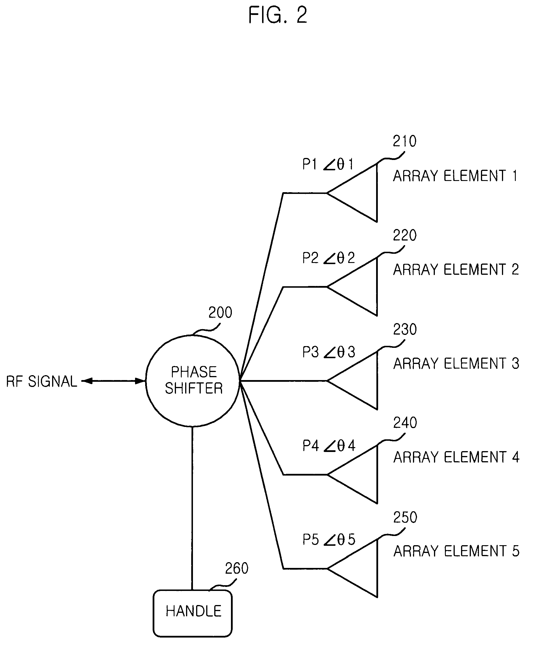
[0032]FIG. 2 is a diagram showing an electrical tilting antenna to which a phase shifter in accordance with the present invention is applied.

[0033]As shown, a phase shifter 200 is electrically connected to five antenna array elements numbered 210, 220, 230, 240 and 250. A first array element 1 (210) has a degree of Θ1 and an amplitude of P1. A second array element 2 (220) has a degree of Θ2 and an amplitude of P2. A fourth array element 4 (240) has a degree of Θ4 and an amplitude of P4. A fifth array element 5 (250) has a degree of Θ5 and an amplitude of P5. A handle 260 controls the phase shifter 200 in such a way that the phase difference between radio frequency (RF) signals fed into the array elements has a scale factor of Θ. In detail, the phase difference between two adjacent RF signal...


PUM


Abstract

Disclosed is a phase shifter having a power dividing function. The phase shifter includes: an input port for receiving a radio frequency (RF) signal; a power dividing unit for dividing the RF signal into a first divided signal of which phase is to be varied and a second divided signal having a fixed phase value; a first output port for outputting the second divided signal having the fixed phase value; a phase shift unit for dividing the first divided signal into a third divided signal and a fourth divided signal wherein the third divided signal and the fourth divided signal move in opposite directions; a phase delay unit for shifting phase of the third divided signal and the fourth divided signal based on a difference in a path length of the third divided signal and the fourth divided signal, to thereby generate phase-shifted signals; and at least two second output ports connected to the phase delay unit, for outputting the phase-shifted signals.

Description

TECHNICAL FIELD[0001]The present invention relates to a phase shifter; and, more particularly, to a phase shifter having power dividing function, which performs tilting of a vertical radiation beam in a base station of a mobile communication system.BACKGROUND ART[0002]In general mobile communication systems, since a density of subscribers is different at every region and at every time, the tilt control is frequently required in order to optimize the mobile communication system. For optimization of the air interface network, in a conventional mobile communication system, a mechanical tilt is used. The beam tilt of the antenna in a vertical direction means an angle of the beam radiated by the antenna slopes to the horizontal.[0003]A conventional antenna is mechanically tilted to vary the radiated beam tilt of the antenna, using a mechanical tilting device mounted on the antenna.[0004]Mechanical tilting of the antenna is a cost-effective way to manufacture the antenna. However, in this...

Claims


Application Information

Patent Timeline
Patent Type & Authority Patents(United States)
IPC IPC(8): H01P1/18H01Q1/24H01Q3/32H01Q3/00
CPCH01P1/184H01Q3/32H01Q1/246H01Q3/00
Inventor TAE, JAE-HOONLEE, YONG-JUKIM, MYOUNG-KUKPARK, JOO-SUNGLEE, JOO-HYUNG
Owner ACE TECH
Why Eureka
Try Eureka