Phase delay linetype reflector element based reflective array antenna

A reflection array antenna and phase delay technology, applied in the field of reflection array antennas and microstrip reflection array antennas, can solve the problems of no obvious advantages, large cross-polarization components, and inability to further improve the gain bandwidth of the reflection array, and achieve the suppression of cross The effect of polarized components

Active Publication Date: 2015-12-09
NAT SPACE SCI CENT CAS
View PDF4 Cites 26 Cited by
  • Summary
  • Abstract
  • Description
  • Claims
  • Application Information

AI Technical Summary

Problems solved by technology

Although the prior art has proposed some phase-delay linear reflectors that can improve the bandwidth of the reflectarray antenna to a certain extent (see references H.Hasani, M.Kamyab, and A.Mirkamali, "Lowcross-polarizationreflectarrayantenna," IEEETrans.AntennasPropag ., vol.59, no.5, pp.1752–1756, May 2011 and references R. Shamsaee and Z. Atlasbaf, “Design and implementation of broadband single layer circularly polarized reflect array antenna,” IEEE Antennas Wireless Propag. Lett., vol.11, pp.973–976, 2012), but Compared with other methods of improving the bandwidth of reflectarray antennas, there is no obvious advantage
The resonant structure adopted by the existing phase delay line reflector has a circular patch or ring structure, which cannot further improve the gain bandwidth of the reflect array, and also has the disadvantage of large cross-polarization components, which makes the phase delay line unit type Microstrip reflectarray antennas still have certain limitations

Method used


Image

  • Phase delay linetype reflector element based reflective array antenna
  • Phase delay linetype reflector element based reflective array antenna
  • Phase delay linetype reflector element based reflective array antenna

Examples


Embodiment

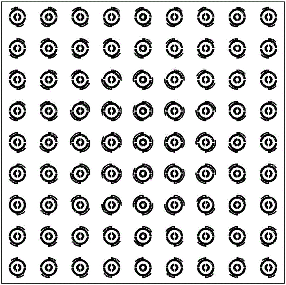
[0028] Such as Figure 1-a with 1-b As shown, the phase delay line unit type microstrip reflectarray antenna of the present invention is composed of 9×9 microstrip reflective unit structures, which are arranged in a mirror-symmetrical manner. This arrangement can effectively reduce the cross-polarized component of the reflector array antenna. The principle is that adjacent reflective units reduce the cross-polarized component of the antenna by partially canceling the line current in the cross-polarized direction on the phase delay line. .

[0029] The design process of the reflectarray antenna is divided into two steps, the first step is the design of the reflector unit, and the second step is the design of the reflector array.

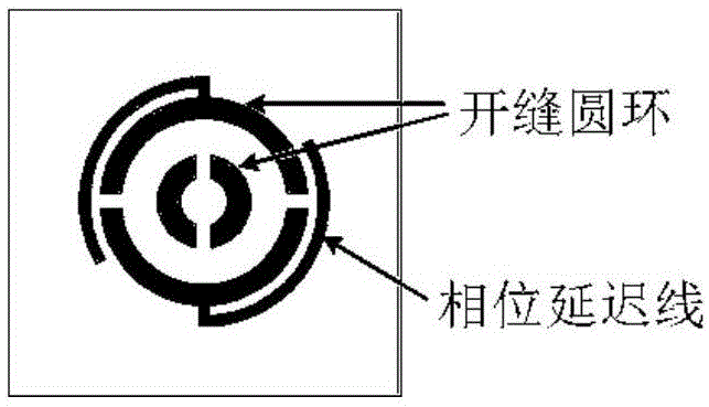
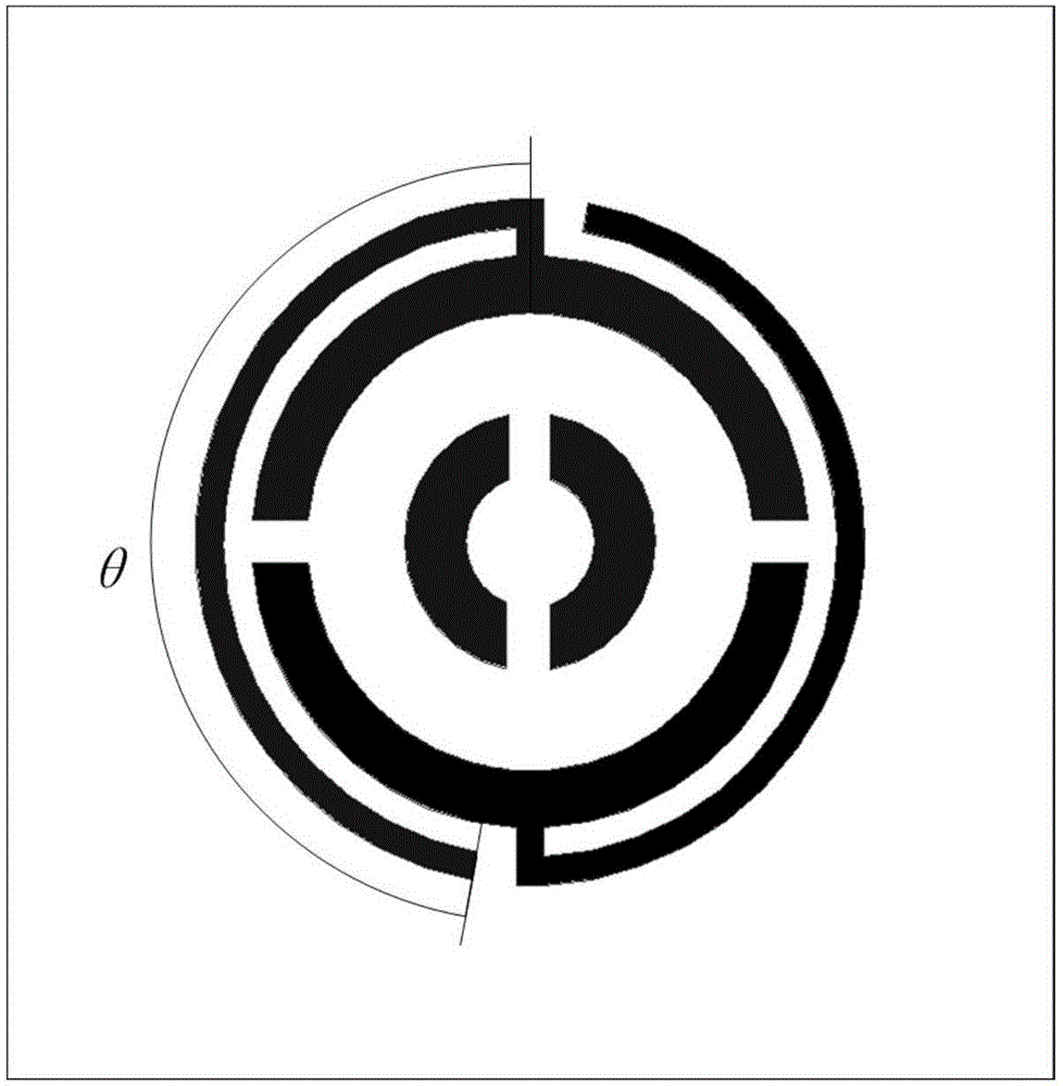
[0030] The first step, reflective unit design. The working frequency of the selected antenna center is 10GHz, such as Figure 2-a with 2-b As shown, the period of the reflection unit is 0.5 times the wavelength, that is, 15 mm. The patch unit is ...


PUM


Abstract

The invention provides a phase delay linetype reflector element based reflective array antenna. The reflective array antenna comprises a pyramid horn feed source and a reflector array, wherein the reflector array is formed by periodically arranging a plurality of phase delay linetype reflector elements in a mirror symmetry manner; and the phase delay linetype reflector element structure comprises two slotting circular ring nests and two phase delay lines that are in opposite in positions. The gain bandwidth of the reflector array antenna is greatly increased, an ultra wide band antenna is realized, and cross polarization is effectively restrained as well; and in addition, the reflection array antenna provided by the invention adopts a single-layer dielectric substrate structure, so that the reflector array is simple in structure, easy to process, low in cost and light in weight.

Description

technical field [0001] The invention belongs to the technical field of antennas, and relates to a microstrip reflection array antenna, in particular to a reflection array antenna based on a phase delay line reflection unit. Background technique [0002] In recent years, microstrip reflectarray antenna technology has been widely used in radar and communication fields due to its outstanding advantages. However, the reflectarray antenna also has some shortcomings, the most important of which is its relatively low bandwidth. There are two reasons for the low bandwidth of the reflectarray antenna: the narrowband characteristics of the microstrip antenna unit itself and the non-constant electrical length of the path between the feed source and the reflector unit. For mid-size reflectarray antennas, the first reason is the most important. [0003] In order to overcome the shortcoming of the narrow frequency band of the reflectarray antenna, many methods have been proposed by the ...

Claims


Application Information

Patent Timeline
Patent Type & Authority Applications(China)
IPC IPC(8): H01Q19/10
Inventor 韩春晖张云华杨青山
Owner NAT SPACE SCI CENT CAS
Why Eureka
Try Eureka