Liquid crystal film structures with phase-retardation surface regions formed therein

a liquid crystal film and surface region technology, applied in the direction of polarising elements, door/window protective devices, instruments, etc., can solve the problems of cholesteric polarizers that are limited in the field of clc-based polarizers to optical applications, and the inherent reduction of brightness by a factor of at least 50 percen

Inactive Publication Date: 2004-05-18
REVEO
View PDF32 Cites 27 Cited by
  • Summary
  • Abstract
  • Description
  • Claims
  • Application Information

AI Technical Summary

Problems solved by technology

Typically, such inefficient conversion of photonic energy results in the production of heat over the surface of the polarizer, causing undesired changes in the polarization characteristics of the polarizer, and at high intensities of incident light, the destruction of the polarizer.
Also, by virtue of the inherent inefficiency of this type of polarizer, the use of dichroic polarizers in the construction of prior art LCD panels causes an inherent reduction in brightness by a factor of at least 50 percent.
In their native form, the prior art CLC-based (i.e. cholesteric) polarizers are limited to optical applications where either left-handed or right-handed circularly polarized light is required, as described above.
While this composite structure can be produce linearly polarizing light without absorbing photonic energy and producing heat, characteristic of dichroic linear polarizers, such a composite linear polarizer suffers from a number of shortcomings and drawbacks.
Also, to avoid delamination of these films, it is necessary to thermally match the coefficients of thermal expansion thereof, which is not easily achieved.
Collectively, these conditions and constraints render the manufacture of such non-absorbing linear polarizers very difficult, and greatly increase the cost of manufacture of such linear polarizing structures that utilizes a quarter-wave retardation.

Method used


Image

  • Liquid crystal film structures with phase-retardation surface regions formed therein
  • Liquid crystal film structures with phase-retardation surface regions formed therein
  • Liquid crystal film structures with phase-retardation surface regions formed therein

Examples


second embodiment

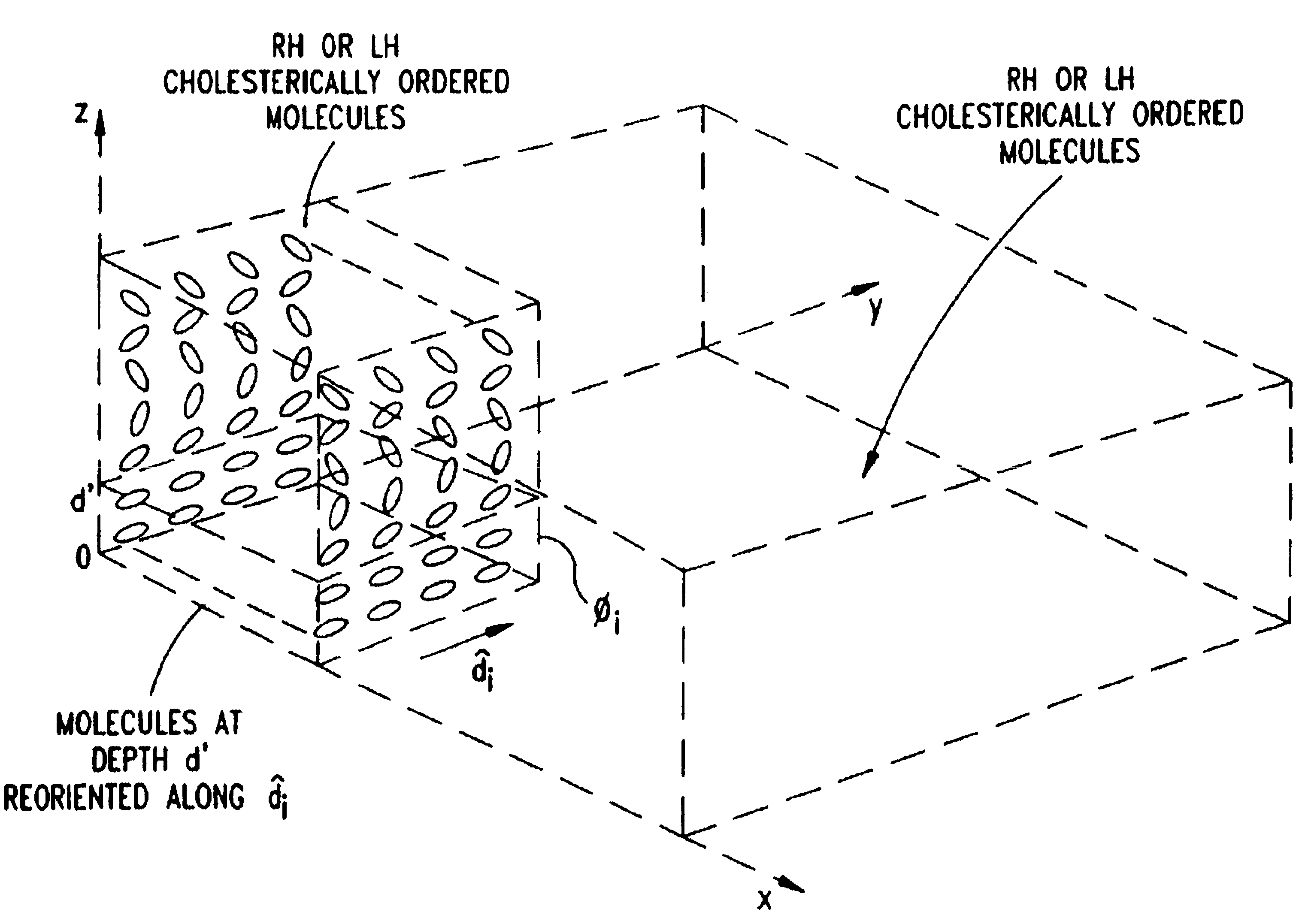
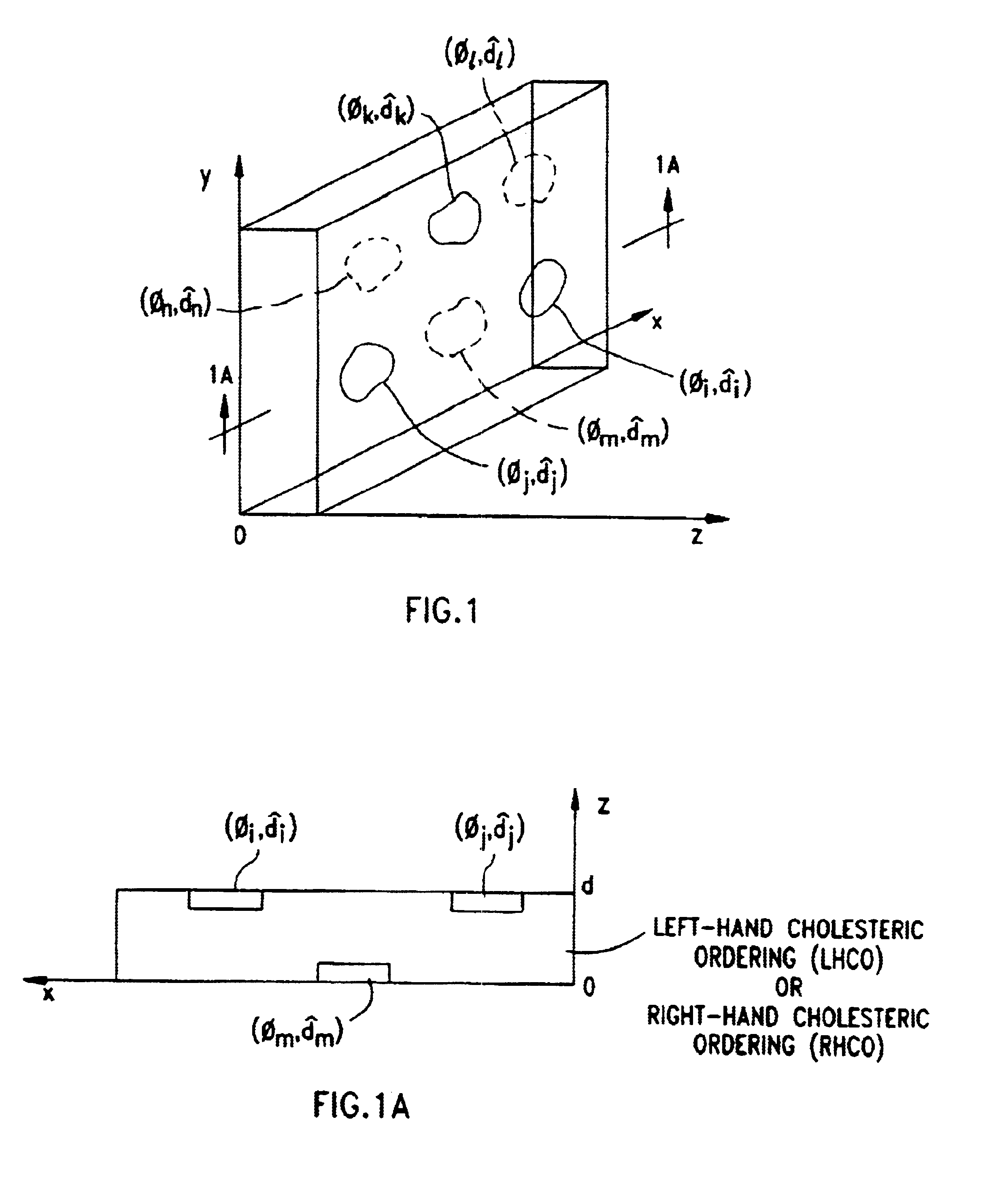
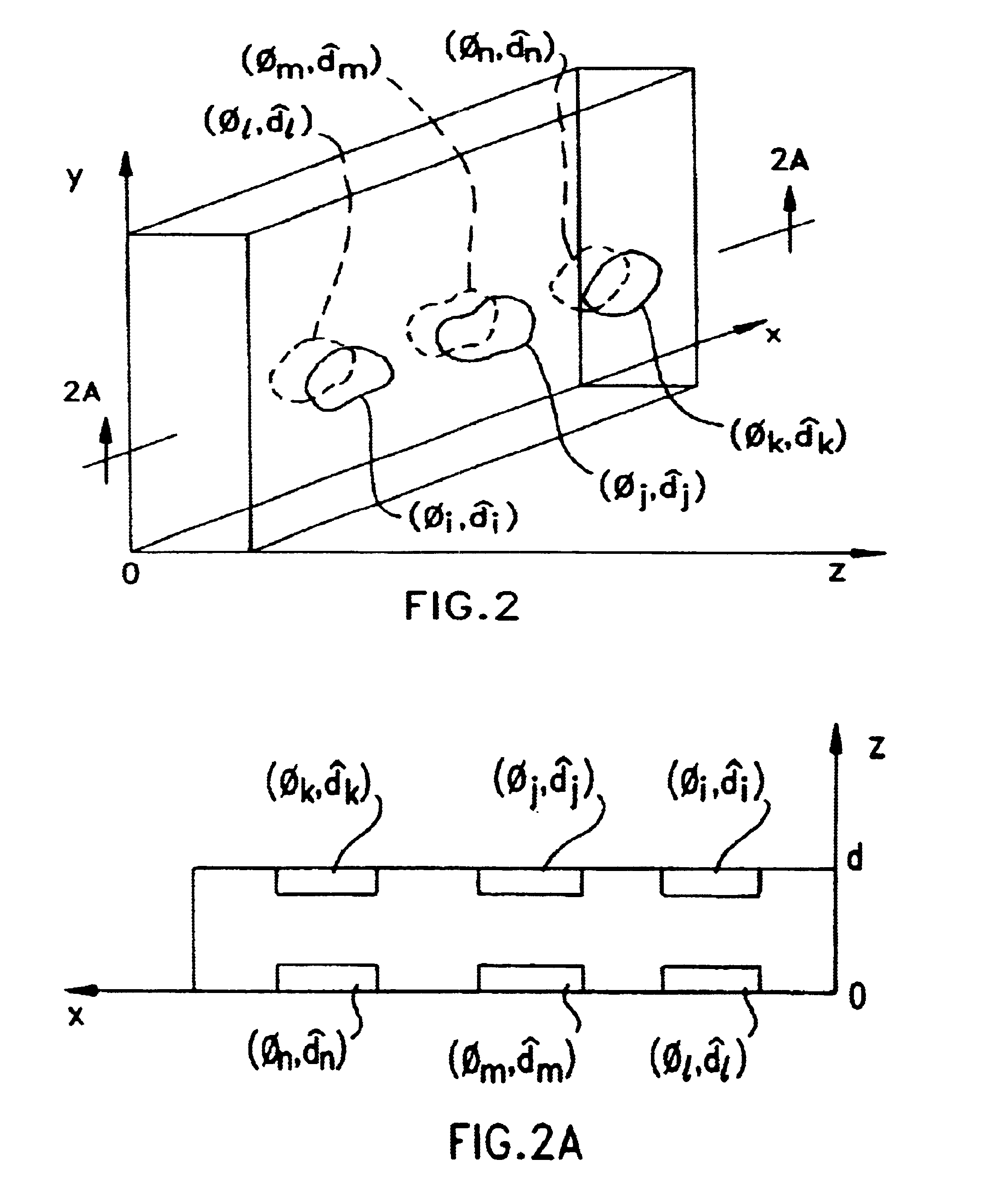
In FIGS. 2 and 2A, the liquid crystal structure of the present invention is schematically illustrated in the form of liquid crystal polarizer. As shown in these figures, the liquid crystal polarizer is realized in the form of a single film structure having (i) a first plurality of birefringent phase retardation regions formed at arbitrary locations on the top surface thereof, (ii) a second plurality of birefringent phase retardation regions formed at spatially-corresponding locations on the top surface thereof in registration with the phase retardation regions on the top surface thereof, and (iii) LH or RH cholesterically ordered molecules disposed therebetween. Each of the birefringent phase retardation regions formed on the top surface of the film structure impart an amount of phase retardation to incident light (of wavelength .lambda.) proportional to depth of reorientation of the cholesterically ordered molecules in the film structure and have an optical axis extending along the...

first embodiment

In FIG. 4B, a fourth broadband embodiment of the liquid crystal polarizer shown in FIG. 4 is shown realized in the form of a single film structure (i.e. sheet) having cholesterically ordered molecules throughout the bulk structure thereof. As shown, the cholesterically ordered molecules have a non-linear pitch between the top and bottom surfaces thereof. Also, a first phase retardation surface is formed on the top surface thereof by orienting the cholesterically ordered molecules at a first depth thereof along a first molecular orientation direction. FIG. 4B1 shows a graphical representation of the pitch characteristics of the cholesterically ordered molecules of the super broadband liquid crystal polarizer of FIG. 4B. As illustrated in this figure, there is the large increase in cholesteric pitch along the surface of the liquid crystal polarizer where the cholesterically ordered molecules have been selectively reoriented to form the birefringent phase-retardation surface structure ...


PUM

PropertyMeasurementUnit
wavelengthsaaaaaaaaaa

Abstract

Disclosed are liquid crystal phase-retarders and linear polarizers and methods and apparatus for making the same. The liquid crystal phase-retarder is realized by a liquid crystal film structure having one or more phase retardation regions formed therein. Each phase retardation region has an optical axis specified by the direction and depth of orientation of liquid crystal molecules along the surface of the liquid crystal film structure. The liquid crystal linear polarizer is realized by a liquid crystal film structure having a chiral phase region within which liquid crystal molecules are cholesterically ordered (FIG. 3). One or more nematic phase regions are formed along the surface of the liquid crystal film structure within which liquid crystal molecules are oriented along a direction and to a surface depth sufficient to realize one or more phase retardation regions therein having optical axes along the direction of liquid crystal molecules orientation.

Description

1. Technical FieldThe present invention relates generally to liquid crystal (LC) phase-retarders realized by a liquid crystal film structure having one or more phase retardation regions formed therein, with each region having an optical axis and a phase retardation specified by the direction and depth of orientation of liquid crystal molecules along the surface of the liquid crystal film structure, and more particularly relates to linear cholesteric liquid crystal (CLC) polarizers realized by forming one or more phase retardation regions within CLC film structures.2. Brief Description of the State of the ArtIn the contemporary period, there is a great need to modulate the spatial intensity of light in liquid crystal display (LCD) panels, optical computing systems, holographic information storage and retrieval systems and the like. In nearly all such optical applications, linear polarizers are required to carry out this light intensity modulation function. In one form or another, a p...

Claims


Application Information

Patent Timeline
Patent Type & Authority Patents(United States)
IPC IPC(8): F24J2/40G02B5/30G02F1/1334G02F1/13C09K19/02C09K19/00E06B9/24
CPCB82Y15/00E06B9/24F24J2/407G02B5/3016E06B2009/2464G02F1/1334Y02E10/40F24S50/80
Inventor FARIS, SADEG MUSTAFA
Owner REVEO
Why Eureka
Try Eureka