
Wireless packet data distributed communications system

a distributed communications and packet data technology, applied in the field of wireless communications, can solve the problems of inefficient power use, significant power consumption, and and achieve the effect of saving power consumption at the expense of terminal communication availability, and avoiding loss of terminal communication availability

Inactive Publication Date: 2009-09-15
2201028 ONTARIO
View PDF103 Cites 18 Cited by
  • Summary
  • Abstract
  • Description
  • Claims
  • Application Information

AI Technical Summary

Benefits of technology

"The invention is a wireless packet data communications system that uses a control station and multiple remote terminals for transmitting and receiving data packets. Each terminal has an address and is assigned specific timeslots on the forward link and the return link for communication. The system uses a hierarchical frame structure with slotted multiple access return link. The return link is preferably CDMA, but other multiple access techniques can also be used. The system allows for synchronization and network status information to be exchanged between the control station and the terminals. The terminals have two oscillators for timing and compensating for frequency errors. The invention allows for waking up specific terminals to receive specific forward link subframes and transmitting a return signal in a specific return subframe to minimize battery drain. The system also allows for time and frequency resynchronization to lower costs and avoid power-consuming crystal ovens."

Problems solved by technology

When the capacity of the terminal's source of power is large relative to the terminal nominal power consumption, such as may be the case when the terminal is powered through an AC connection, inefficient use of power may be tolerable.
For such a system, a terminal may be required to continually monitor its receive channel and hence endure significant power consumption during periods of communications inactivity.
The savings in power consumption, however, occur at the expense of terminal communications availability.
For such a case, the terminal is said to have a low availability.
In this case, the low power consumption achieved by the terminal using sleep mode occurs at the expense of bandwidth efficiency.
Mandatory periodic communications between each terminal and a base station, such as occurs in cellular systems, results in inefficient use of the communications channel, particularly for those applications where the nominal sleep period for communications between a terminal and end-user is significantly greater than the period of the mandatory communications.
For such applications, the battery lifetime of the terminals using the concept of U.S. Pat. No. 5,392,287 would be unduly limited.
This results and considerable power drain since the terminal must receive a block of data.
Furthermore, while it may be desirable to have a terminal monitor the communications channel periodically to determine if there any messages or packets, it is not desirable in terms of the bandwidth efficiency to have the earth station transmit a message at each occurrence of a terminal's active state dedicated to that terminal.
The communications overhead associated with the requirement to transmit a dedicated message to each terminal during its active state severely limits the capacity of the system.

Method used


Image

  • Wireless packet data distributed communications system
  • Wireless packet data distributed communications system
  • Wireless packet data distributed communications system

Examples


Embodiment Construction

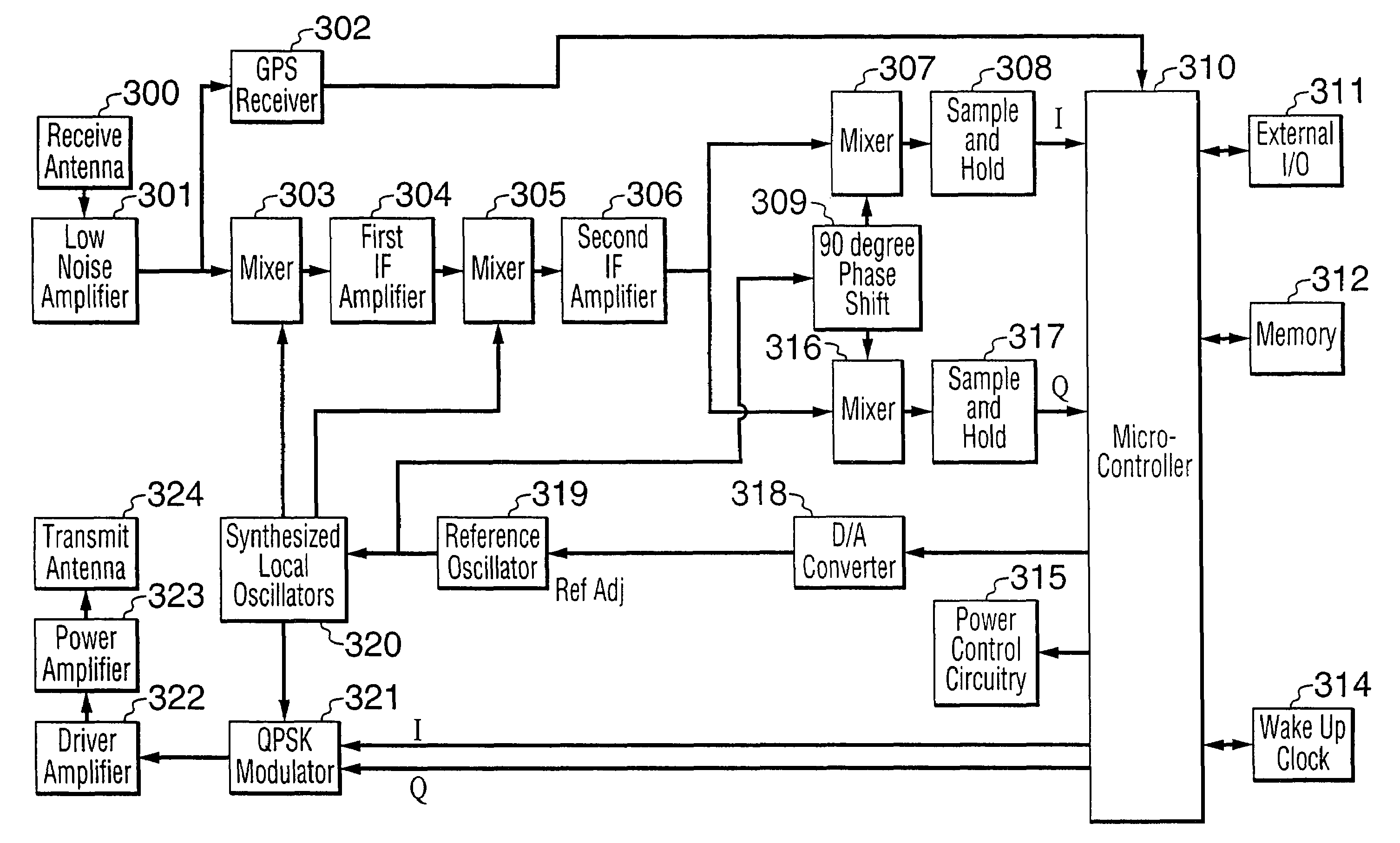
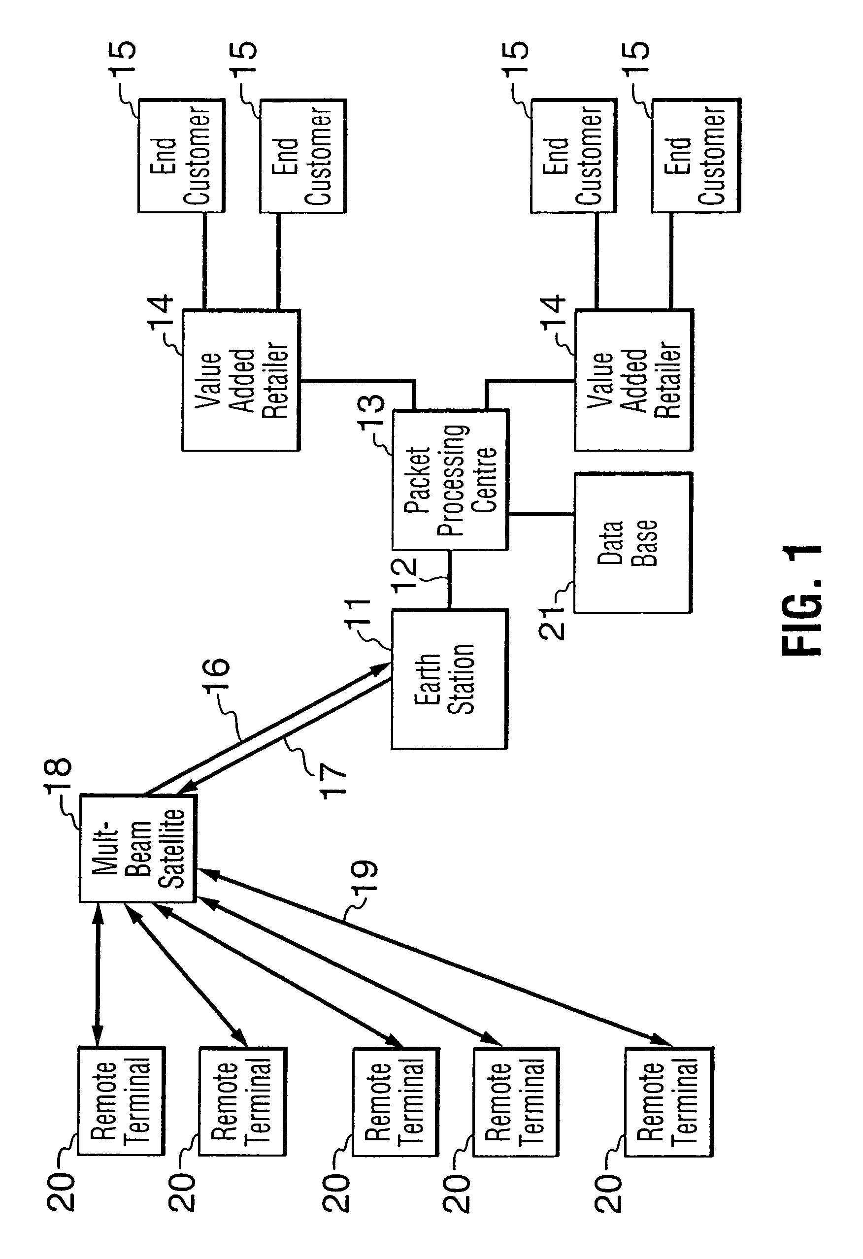
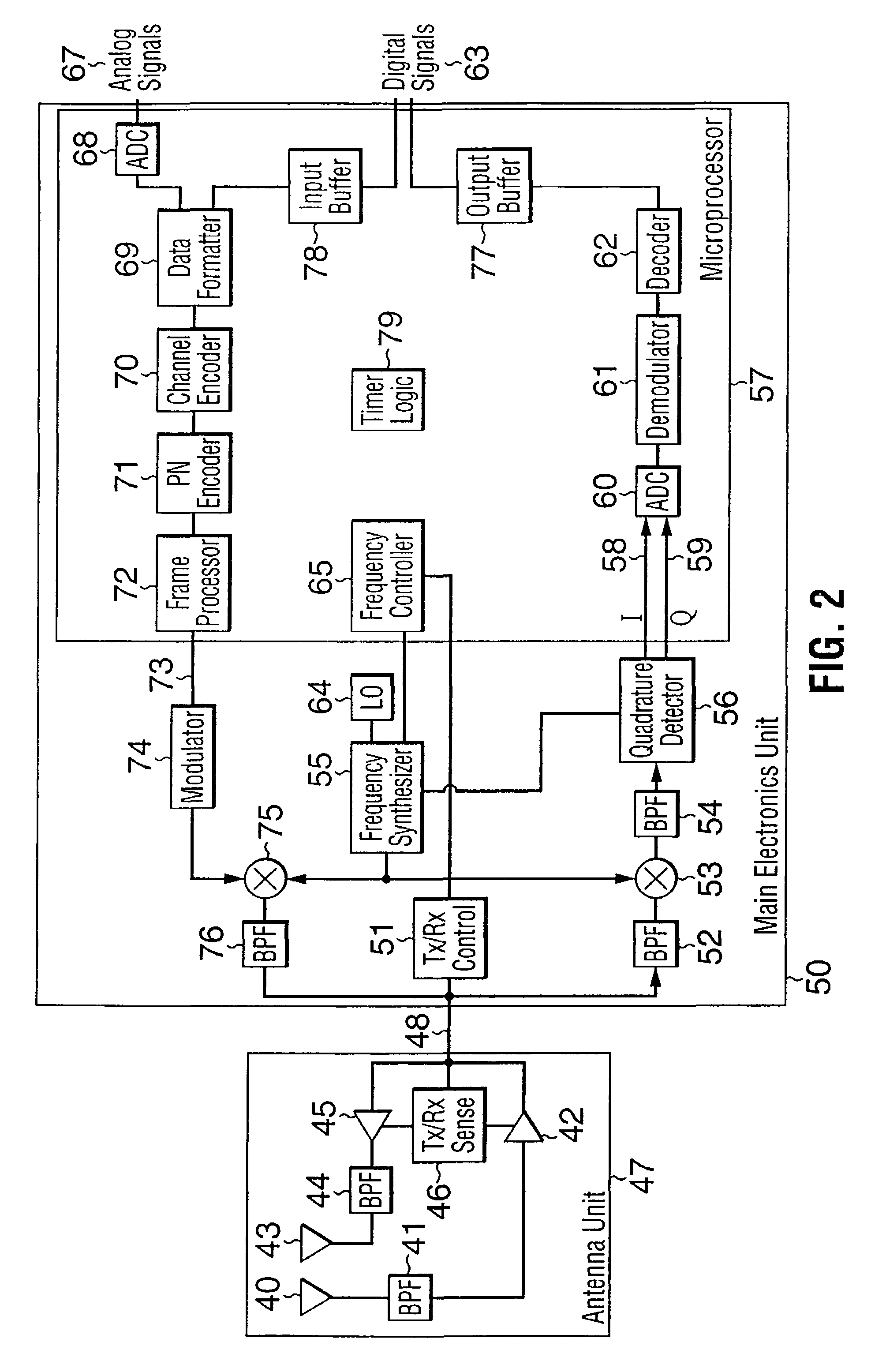
[0084]Referring now to FIG. 1, the satellite communications system consists of a central Earth station 11 which is connected over a wired connection 12, for example, through a public switched network, to a packet processing center 13, normally operated by a service provider, which in turn is connected over a wired connection path to a value added retailer 14 and ultimately to one or more end customers 15. The packet processing center 13 includes a database 21 that stores information pertaining to the subframes allocated to particular terminals in a manner to be described in more detail below. The PPC 13 also stores beam information when multiple beam satellites are employed.

[0085]The Earth station 11 is also coupled by satellite links 16, 17 to a geostationary multi-beam satellite 18 which relays the signals via links 19 to and from a plurality of remote terminals 20, typically mounted on vehicles, such as helicopters, truck trailers, passenger cars, and rail cars. The satellite 18 ...


PUM


Abstract

A two-way satellite communications system includes an Earth station communicating with a plurality of remote terminals using a network access protocol that facilitates low power consumption by the terminals. The earth station generates forward link TDM packet data transmissions on one or more satellite channels, and detects, despreads and decodes multiple concurrent return link slotted CDMA packet transmissions on one or more satellite channels. It communicates through a wired connection with a packet processing center which ultimately both delivers return link packet data to end-customers and receives forward link packet data from end-customers. The remote terminals receive, process and act upon forward link TDM transmissions on one or more satellite channels, and generate slotted spread spectrum CDMA transmissions on the return link on one or more satellite channels. The remote terminals communicate with a local digital data source and / or sink, digitize one or more local analog sensor signals, enter into a sleep mode to minimize the terminal's power consumption, and access the satellite communications network in accordance with the system network access protocol.

Description

[0001]This application is a continuation of our application Ser. No. 10 / 096,492 filed on Mar. 13, 2002, now U.S. Pat. No. 7,142,521, which is a continuation of application Ser. No. 09 / 430,140 filed on Oct. 29, 1999 (now abandoned), which is a continuation of our application Ser. No. 08 / 760,208 filed on Dec. 4, 1996, now U.S. Pat. No. 5,991,279, which in turn claims priority under 35 U.S.C. 199(e) from our provisional application Nos. 60 / 008,320 filed on Dec. 7, 1995 and 60 / 018,183 filed on May 23, 1996.BACKGROUND OF THE INVENTION[0002]The present invention relates to wireless communications, and more particularly, to a system for establishing two-way packet data communications, preferably by satellite, between a control station, the earth station in a satellite-based system, and a plurality of widely dispersed remote terminals. The system may be used to provide a communications conduit between a remote information source and / or sink and a fixed controlling and / or monitoring station....

Claims


Application Information

Patent Timeline
Patent Type & Authority Patents(United States)
IPC IPC(8): H04B7/216
CPCH04B7/2041H04B7/216H04B7/2046Y02D30/70
Inventor HAUGLI, HANS-CHRISTIANSEED, WILLIAM ROBERT
Owner 2201028 ONTARIO
Learn More