Hydraulic accumulator

Active Publication Date: 2009-09-22
HYDAC TECH GMBH
View PDF19 Cites 2 Cited by
  • Summary
  • Abstract
  • Description
  • Claims
  • Application Information

AI Technical Summary

Benefits of technology

[0009]This object is basically achieved by a hydraulic accumulator with a gas-tight and / or fluid-tight sealing of at least one working chamber relative to the exterior. The associatable, advanced free longitudinal edge of the accumulator housing is connected to the respective cover part by a peripheral weld. Reliable sealing is obtained by the weld. Moreover, the weld provides a reliable connection between the free longitudinal edge and the respective cover part so that failure is reliably prevented, even when correspondingly high pressure peaks are experienced. On the whole, the connection stability for the accumulator solution can be increased by the peripheral weld.
[0010]The placement of the cover part in the accumulator housing, the preparation of a clamping seat between the free longitudinal end of the accumulator housing and the cover part, and the formation of the peripheral weld in the described region can be easily and economically accomplished. The described solution can then be implemented as a disposable concept without having to maintain these cheap accumulator solutions, especially not to refill them on the gas side with the working gas, but to dispose of them in case of maintenance or failure and replace them by a new cheap accumulator.
[0011]In one preferred embodiment of the hydraulic accumulator of the present invention, at least one of the two cover parts is provided on its one side with a conically extending fixing bevel against which the free longitudinal edge of the accumulator housing is advanced. Preferably, between the end of the free longitudinal edge of the accumulator housing and the fixing bevel of the cover part, a preferably V-shaped fillet groove is formed which holds the weld. This fillet groove dictates a guide path for the peripheral weld to be formed, and facilitates the weld production process accordingly.

Problems solved by technology

Producing this threaded connection is time-consuming, making the production costs for a piston accumulator accordingly higher.
Although for the above-described hydraulic accumulator solution the cover part is provided with sealing means, especially in the form of gaskets, it cannot be precluded that especially at high pressures in the working chambers and / or for correspondingly long service lives the medium stored in the working chamber unintentionally travels to the exterior.
Viewed over the long-term, this gas escape degrades the operating reliability of the hydraulic accumulator.
This adding of has, however, is accompanied by the corresponding maintenance cost which is especially undesirable if the designed hydraulic accumulators are to be used in the form of a disposable solution on site within the hydraulic system only for a predetermined time.

Method used


Image

  • Hydraulic accumulator
  • Hydraulic accumulator

Examples


Embodiment Construction

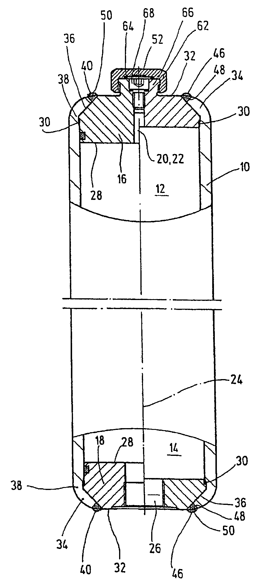
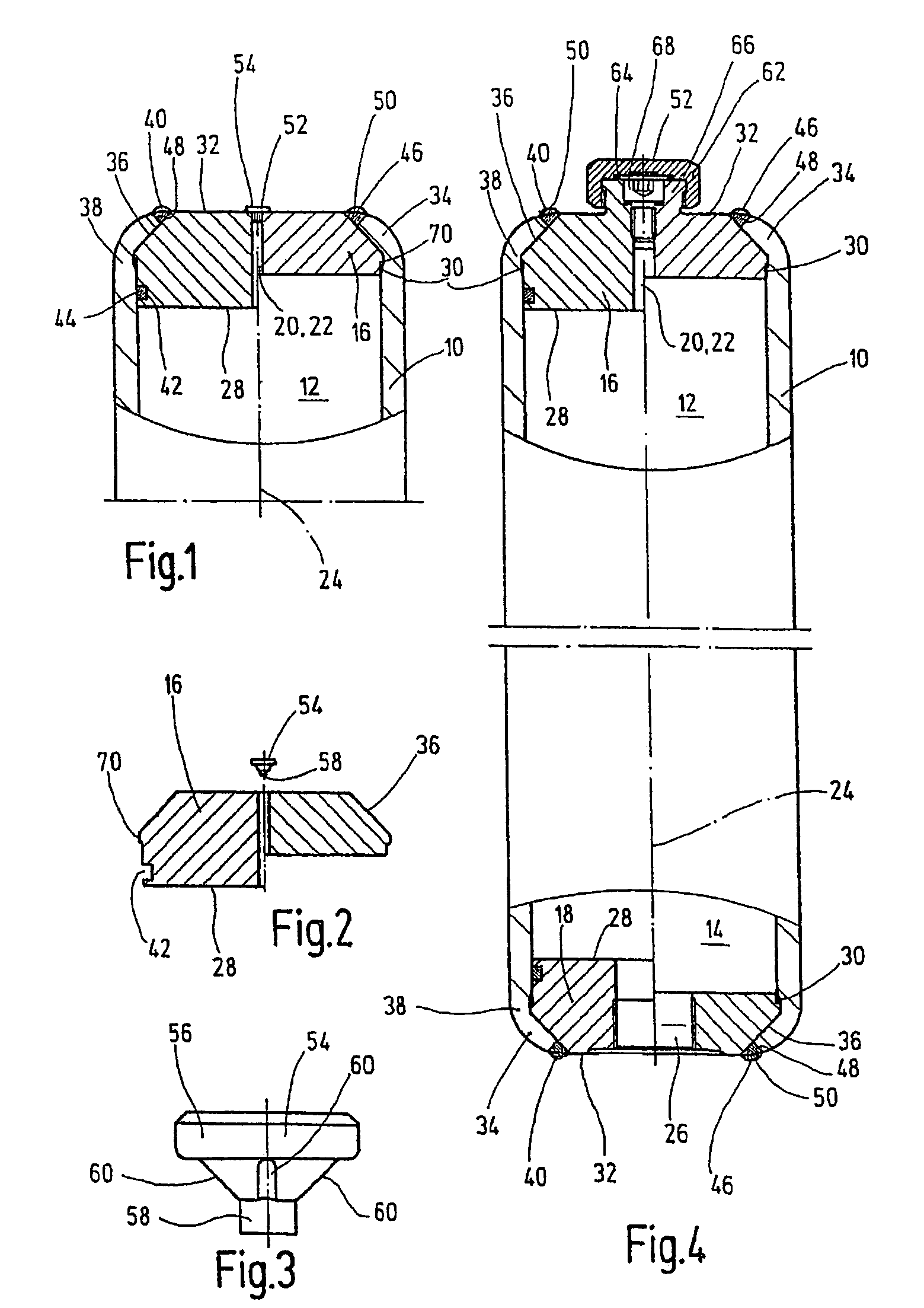
[0020]The piston accumulator 10 shown in FIG. 1 has an accumulator housing 10 formed as an outer cylinder pipe. The separating element is a piston (not detailed) with its sealing system on the outer peripheral side inserted into and movable longitudinally in housing 10. These piston accumulators with pistons as the separating element are known in a host of designs, and are described for example in the state of the art in DE 103 03 988 A1. The piston within the accumulator housing 10 separates two working chambers 12, 14 (FIG. 4) from one another, one or a first working chamber 12 being used to hold the working gas, especially in the form of nitrogen, and the other, second working chamber 14 forming the so-called liquid chamber for the piston accumulator. Depending on the operating situation of the accumulator, the movement positions of the piston and the volumetric portions of gas and fluid in the working chambers 12 and 14 vary.

[0021]On each front end of the accumulator housing 10,...


PUM


Abstract

A hydraulic accumulator, especially a piston accumulator includes an accumulator housing (10) and a separating piston that can be longitudinally displaced in the accumulator housing (10) and divides two working chambers (12) inside the accumulator housing (10). The housing is sealed on each end by one cover part (16). At least one cover part is fixed, on one side (32) by a free longitudinal edge (34) of the accumulator housing (10). The edge is arranged against the cover part (16). By connecting the free longitudinal edge (34) of the accumulator housing (10) to the associated cover part (16) by a peripheral weld seam (46) for sealing at least one working chamber (12) from the environment in a gas-tight and / or fluid-tight manner, a reliable sealing is obtained by the weld seam (46). The weld seam also connects the free longitudinal edge (34) of the accumulator housing (10) to the associated cover part (16).

Description

FIELD OF THE INVENTION[0001]The present invention relates to a hydraulic accumulator, in particular a piston accumulator, having an accumulator housing, and a separator piston movable in the longitudinal direction in the accumulator housing. The piston separates two working chambers from one another within the accumulator housing. The housing is closed on each end side by a cover part, at least one cover part on its one side being fixed by one free longitudinal edge of the accumulator housing, which edge is advanced onto this cover part for this purpose.BACKGROUND OF THE INVENTION[0002]Piston accumulators are in the broadest sense hydraulic accumulators used among other things to hold certain volumes of a pressurized liquid (hydraulic medium) of a hydraulic system and to return it if necessary to the system. Since the hydraulic medium is under pressure, hydraulic accumulators are treated like pressure vessels and must be designed for the maximum operating overpressure with considera...

Claims


Application Information

Patent Timeline
IPC IPC(8): F15B1/04
CPCF15B1/16F15B1/24F15B2201/605F15B2201/312F15B2201/415F15B2201/205
Inventor KORT, ARMIN
Owner HYDAC TECH GMBH
Why Eureka
Try Eureka