Thermoluminescent dosimeter for radiation monitoring, comprising LiF doped with Mg, Cu, and Si, and fabrication method thereof

a technology of thermoluminescent dosimeters and radiation monitoring, which is applied in the direction of x/gamma/cosmic radiation measurement, dosimeters, instruments, etc., can solve the problems of reducing sensitivity, affecting the accuracy of radiation monitoring, and reducing the intensity of thermoluminescent (tl) intensity, etc., to achieve excellent densimetric characteristics, reduce the intensity of radiation monitoring, and reduce the residual signal

Active Publication Date: 2009-09-22
KOREA ATOMIC ENERGY RES INST +1
View PDF3 Cites 2 Cited by
  • Summary
  • Abstract
  • Description
  • Claims
  • Application Information

AI Technical Summary

Benefits of technology

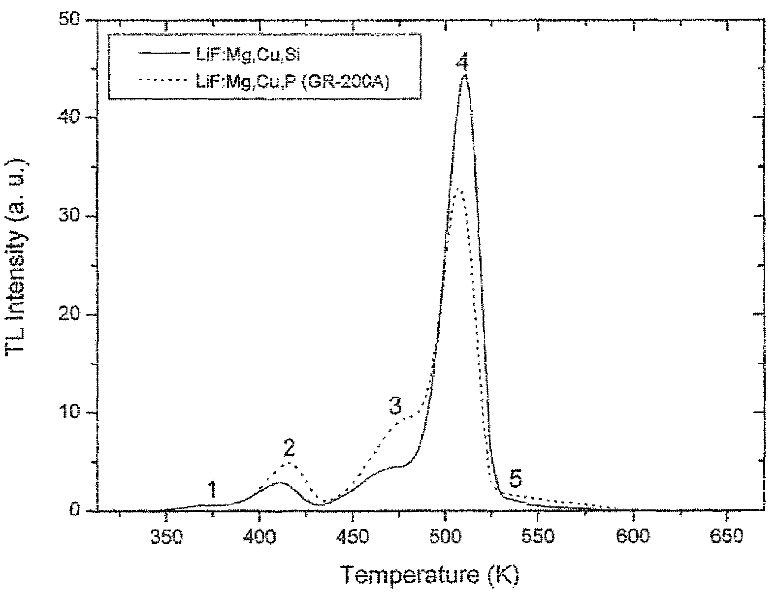
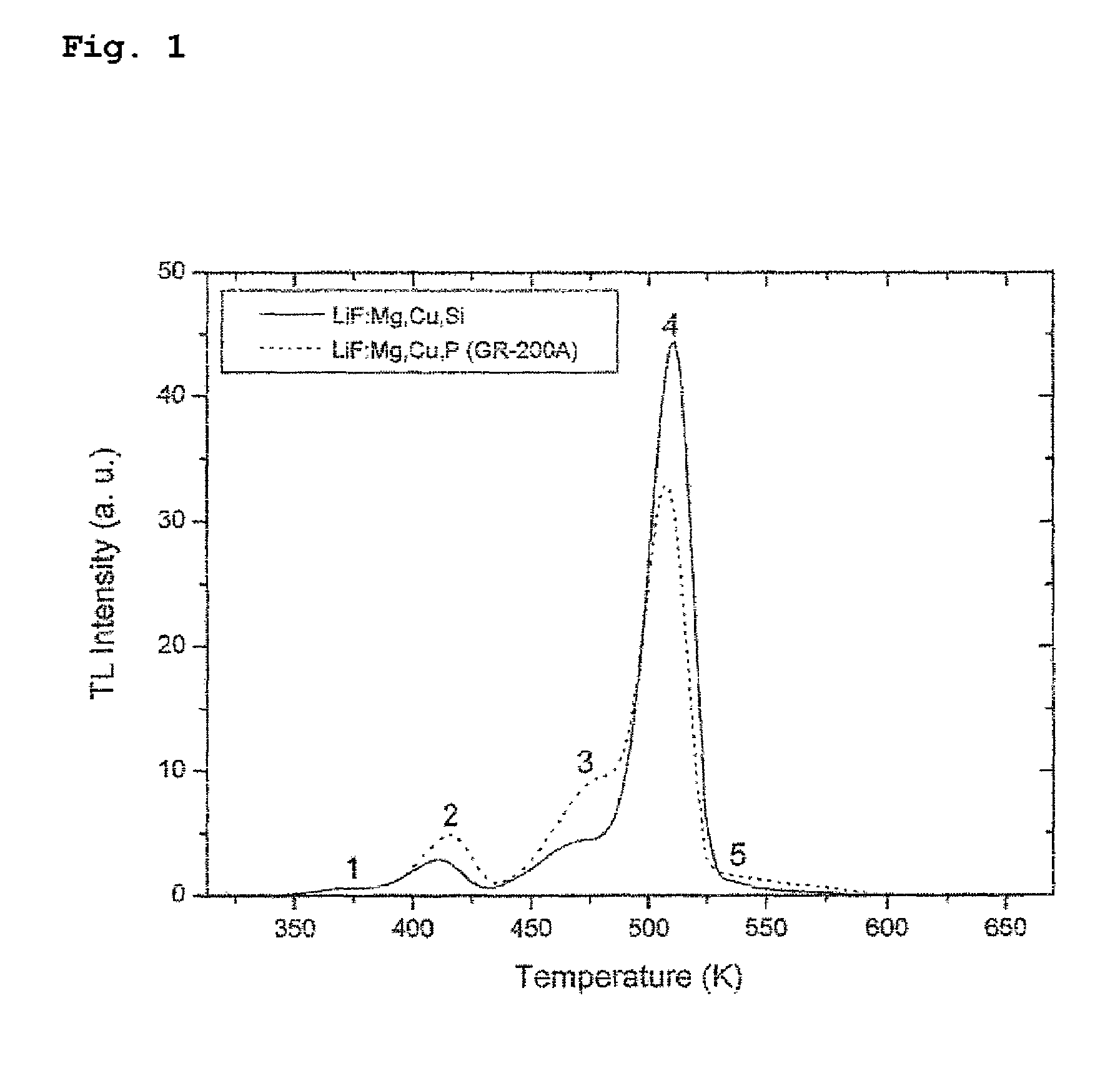
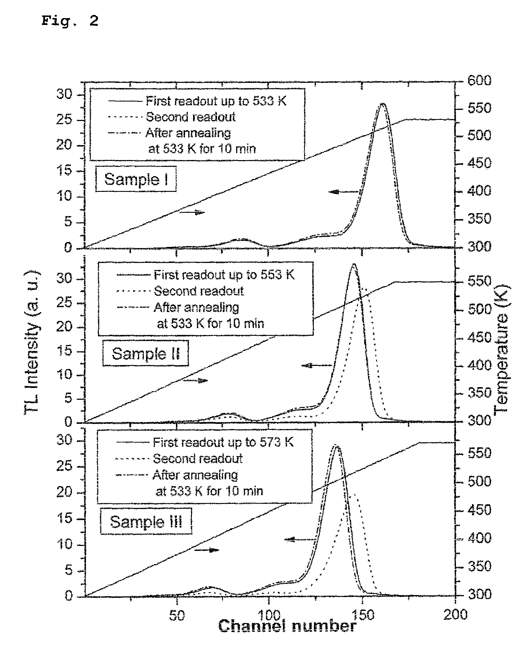
[0019]Accordingly, it is an object of the present invention to provide a thermoluminescent dosimeter comprising LiF doped with Mg, Cu and Si, which has excellent densimetric characteristics and a low residual signal, has reduced thermoluminescent (TL) intensity in a higher temperature range of the main glow peak, leading to a residual signal markedly lower than that of the prior thermoluminescent dosimeter, and high thermal stability, and can maintain the same sensitivity as its initial readout value when it is reused.

Problems solved by technology

When electrons in the trapping level have no thermal disturbance, they may remain in these traps for a considerably long period of time.
However, this material has two major disadvantages in that it shows a rapid reduction in sensitivity when annealed at a temperature higher than 240° C., and in that it has a relatively high residual signal.

Method used


Image

  • Thermoluminescent dosimeter for radiation monitoring, comprising LiF doped with Mg, Cu, and Si, and fabrication method thereof
  • Thermoluminescent dosimeter for radiation monitoring, comprising LiF doped with Mg, Cu, and Si, and fabrication method thereof
  • Thermoluminescent dosimeter for radiation monitoring, comprising LiF doped with Mg, Cu, and Si, and fabrication method thereof

Examples


example 1

Fabrication of Thermoluminescent Element for Radiation Monitoring, Comprising LiF Doped with Mg, Cu and Si

[0053]To 99.9% pure LiF, 0.45 mol % of MgSO4. 7H2O, 0.025 mol % of CuSO4. 5H2O, and 0.9 mol % of SiO2 nanopowder were added as dopants. Then, the components were uniformly mixed in distilled water using a magnetic stirrer. The mixture was dried on a hot plate at 150° C. with the operation of a magnetic stirrer, after which it was placed in a platinum crucible and heated and melted in an electric furnace under an air atmosphere at 1050° C. for 30 minutes, thus activating the mixture. Then, the melted material was rapidly cooled on a previously prepared copper plate having a temperature of −20° C. The cooled material was ground, and sieved through a standard sieve to extract a crystal material having a grain size of 40-150 μm. The extracted crystal material was washed with HCl solution and then with distilled water, and treated with acetone, followed by drying. The powder material...


PUM

PropertyMeasurementUnit
temperatureaaaaaaaaaa

Abstract

Disclosed herein are a thermoluminescent dosimeter for radiation monitoring, comprising LiF doped with Mg, Cu and Si, and a fabrication method thereof. The LiF:Mg,Cu,Si thermoluminescent dosimeter is fabricated by heating a LiF-based thermoluminescent powder material having a composition of LiF mother material, 0.1-0.5 mol % of a Mg compound, 0.001-0.05 mol % of a Cu compound and 0.5-1.3 mol % of a Si compound to a temperature of 900-1200° C. to melt the LiF-based material, cooling the melted material, compression-molding the cooled material, sintering the molded material, cooling the sintered material, and then annealing the cooled material. The thermoluminescent dosimeter has high thermal stability and thus maintains constant thermoluminescence sensitivity even when it is annealed at a high temperature of more than 240° C. Moreover, it has a remarkably low residual signal, and shows excellent dosimetric characteristics, because it can maintain the same sensitivity as its initial readout value, even when it is reused.

Description

CROSS-REFERENCE TO RELATED APPLICATION[0001]This application claims the benefit of Korean Patent Application No. 10-2006-075535, filed Aug. 10, 2006 in the Korean Intellectual Property Office, the disclosure of which is incorporated herein in its entirety by reference.BACKGROUND OF THE INVENTION[0002]1. Field of the Invention[0003]The present invention relates to a thermoluminescent dosimeter for radiation monitoring, comprising LiF doped with Mg, Cu and Si, and a fabrication method thereof. Particularly, the present invention relates to a thermoluminescent dosimeter that shows high thermal stability and thus maintains constant sensitivity even upon high-temperature annealing, has a remarkably low residual signal, and can maintain the same sensitivity as its initial readout value even when it is reused.[0004]2. Description of the Prior Art[0005]Various types of thermoluminescent detectors for detecting radiation employ various principles in various application fields. Examples there...

Claims


Application Information

Patent Timeline
Patent Type & Authority Patents(United States)
IPC IPC(8): H05B33/00G01T1/10
CPCG01T1/11B29C43/00
Inventor KIM, JANG-LYULLEE, JUNG-ILYANG, JEONG-SUNKIM, BONG-HWANKIM, JONG-SOO
Owner KOREA ATOMIC ENERGY RES INST
Why Eureka
Try Eureka