Method and device for configuration examination

a configuration and configuration technology, applied in the direction of optical radiation measurement, instruments, spectrometry/spectrophotometry/monochromators, etc., can solve the problem of not quantitatively evaluating the defect of an object without a pipe-shaped configuration, the size and shape of the three-dimensional configuration of the defect may not be quantitatively evaluated, and the measurement of the defect from an irradiated direction may not be obtained

Inactive Publication Date: 2009-09-22
AISIN SEIKI KK
View PDF9 Cites 4 Cited by
  • Summary
  • Abstract
  • Description
  • Claims
  • Application Information

AI Technical Summary

Problems solved by technology

However, the transparent intensity of the electromagnetic wave is influenced by a defect inside of the object and compositional homogeneity of composition of the object, for example.
Therefore, measurement of the defect from an irradiated direction may not be obtained.
However, the defect of an object without a pipe-shaped configuration may not be quantitatively evaluated.
Accordingly, size and shape as three-dimensional configuration of the defect may not be quantitatively evaluated.

Method used


Image

  • Method and device for configuration examination
  • Method and device for configuration examination
  • Method and device for configuration examination

Examples


Embodiment Construction

[0022]An embodiment of the present invention will be described hereinafter with reference to attached drawings. Components possessing the same general configuration between each drawing will be denoted with the same reference numerals and duplicated explanation will be omitted herein.

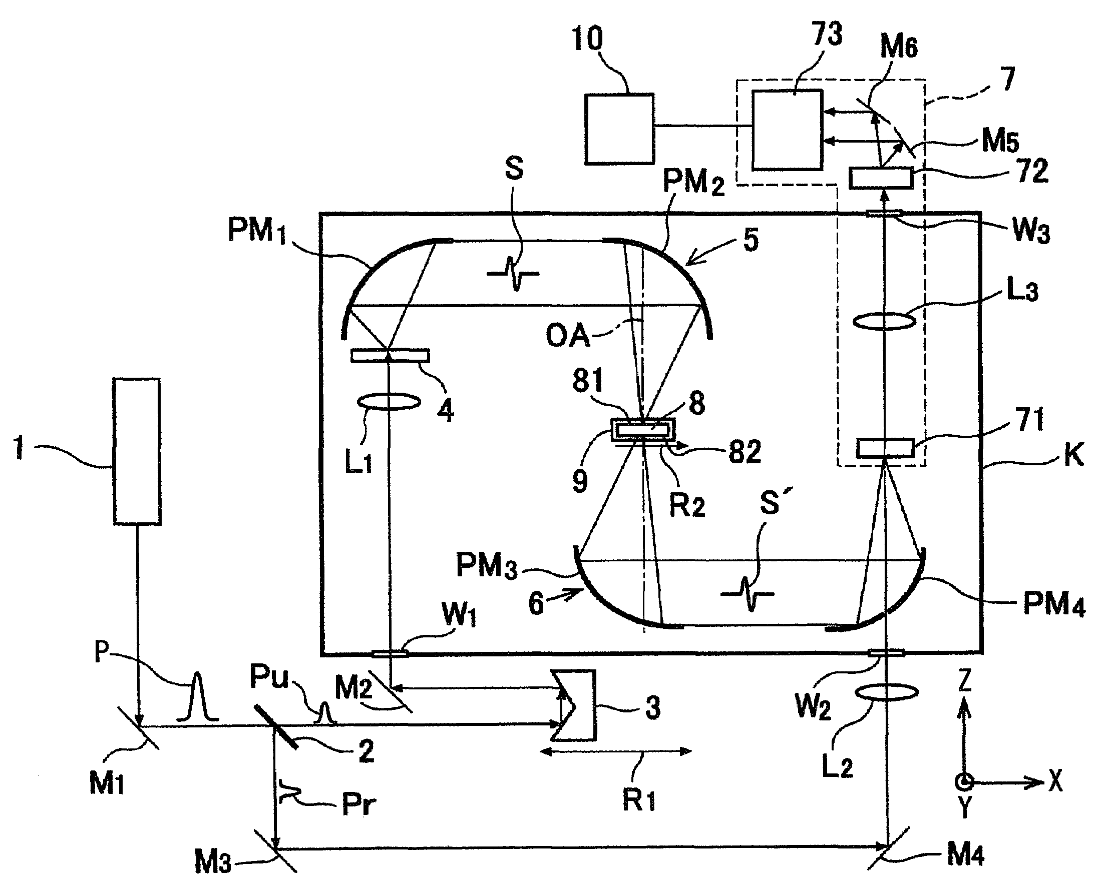
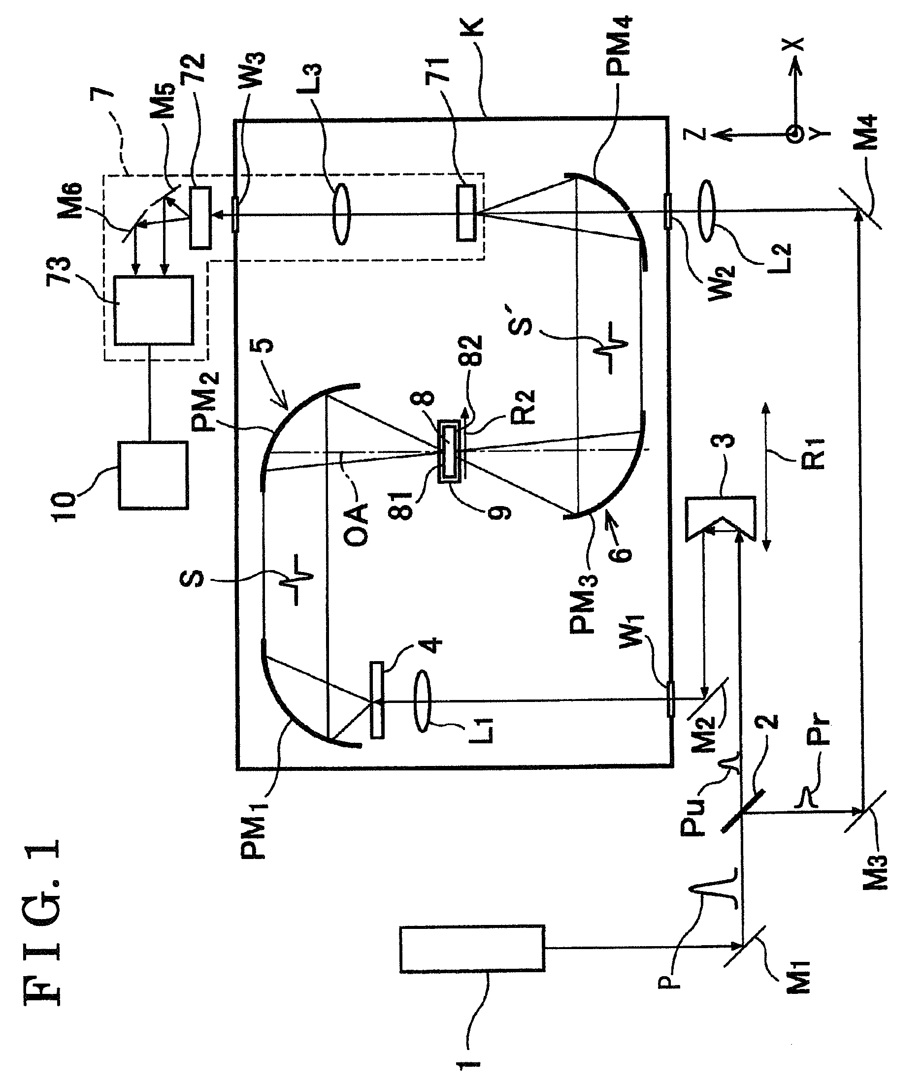
[0023]FIG. 1 is a schematic overview illustrating a configuration examination device according to the present invention. As illustrated in FIG. 1, the configuration examination device includes a laser light source 1, a light dividing portion 2, a light-delay controlling portion 3, a terahertz pulsed light generating portion 4, a light-irradiating portion 5, a moving portion 9, a light-receiving portion 6, a detecting portion 7, and a configuration judging portion 10. With reference to FIG. 1, M1 to M6 represent planar mirrors and L1 to L3 represent lenses. Additionally, PM1 to PM 4 represent off-axis parabolic mirrors and W1 to W3 represent windows. A housing K isolates light paths of terahertz pulsed l...


PUM

PropertyMeasurementUnit
frequencyaaaaaaaaaa
poweraaaaaaaaaa
diameteraaaaaaaaaa

Abstract

A method of examining a configuration of a sample includes the step of irradiating a terahertz pulsed light, which possesses a wavelength to transmit through the sample, to at least two different portions of the sample, the step of detecting at least two electric field amplitude-time resolved waveforms of the terahertz pulsed light transmitted through the first and second portions of the object to be examined, and the step of examining the configuration of the sample based upon phase information obtained from the electric field amplitude-time resolved waveforms detected.

Description

CROSS REFERENCE TO RELATED APPLICATIONS[0001]This application is based on and claims priority under 35 U.S.C. § 119 to Japanese Patent Application 2006-276513, filed on Oct. 10, 2006, the entire content of which is incorporated herein by reference.FIELD OF THE INVENTION[0002]The present invention generally relates to a method and a device for examining a configuration of an object manufactured by injection molding, compression molding, extrusion molding, or the like. More specifically, the present invention relates to a method and a device for irradiating an electromagnetic wave through a sample and examining a bump and a configuration of the sample by a change of the electromagnetic wave passing through the object.BACKGROUND[0003]Resin-made components are frequently employed as components of vehicles, digital products, or the like, in place of metal materials in order to reduce weight and cost. Particularly in vehicle components, various sensors are mounted on the vehicles for a hi...

Claims


Application Information

Patent Timeline
Patent Type & Authority Patents(United States)
IPC IPC(8): G01N21/00G01B11/24G01B11/30G01N21/88
CPCG01N21/3581H01S1/02G01N21/958
Inventor OHTAKE, HIDEYUKISUGIURA, TOSHIHARU
Owner AISIN SEIKI KK
Why Eureka
Try Eureka