

Recording disk driving device motor unit having a sheet member attached to a base
a technology of driving device and recording disk, which is applied in the direction of dynamo-electric machines, dynamo-electric components, instruments, etc., can solve the problems of not easy to stick the fpc, achieve the effect of suppressing the deformation of the base portion in the mounting of the recording disk, facilitating the positioning of the sheet-shaped member, and increasing the efficiency of sticking operation
- Summary
- Abstract
- Description
- Claims
- Application Information
AI Technical Summary
Benefits of technology
Problems solved by technology
Method used
Image

Examples
first embodiment
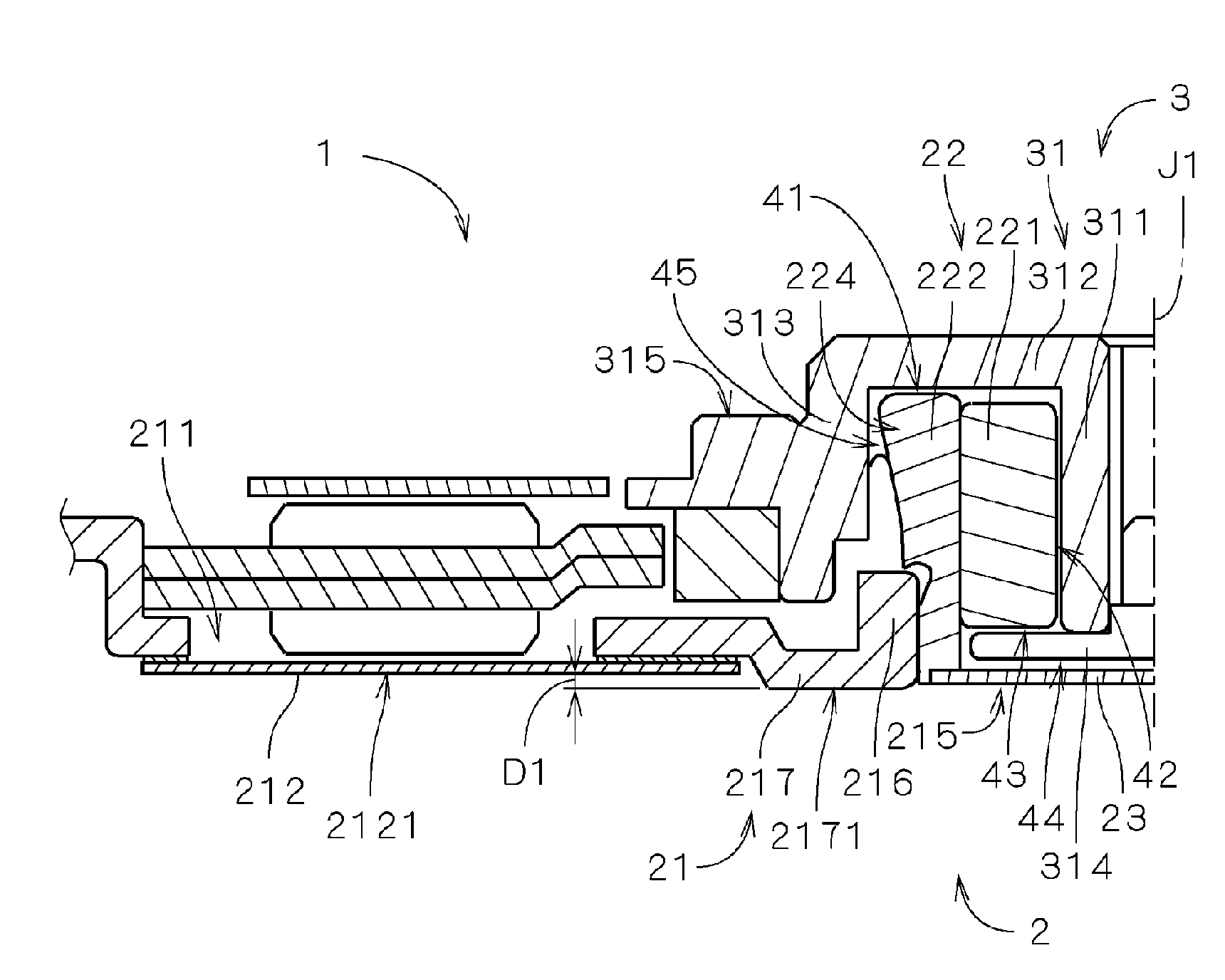
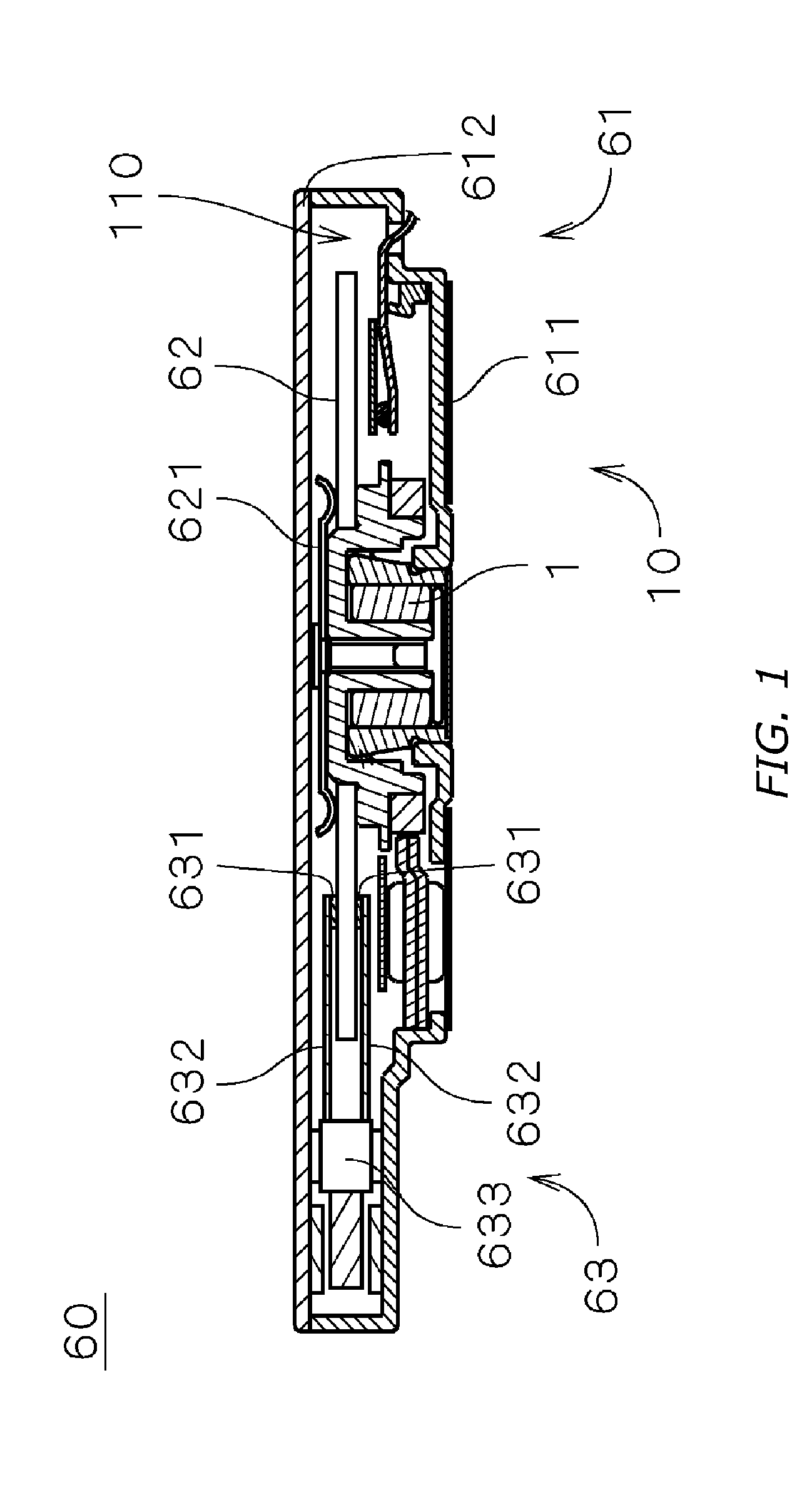
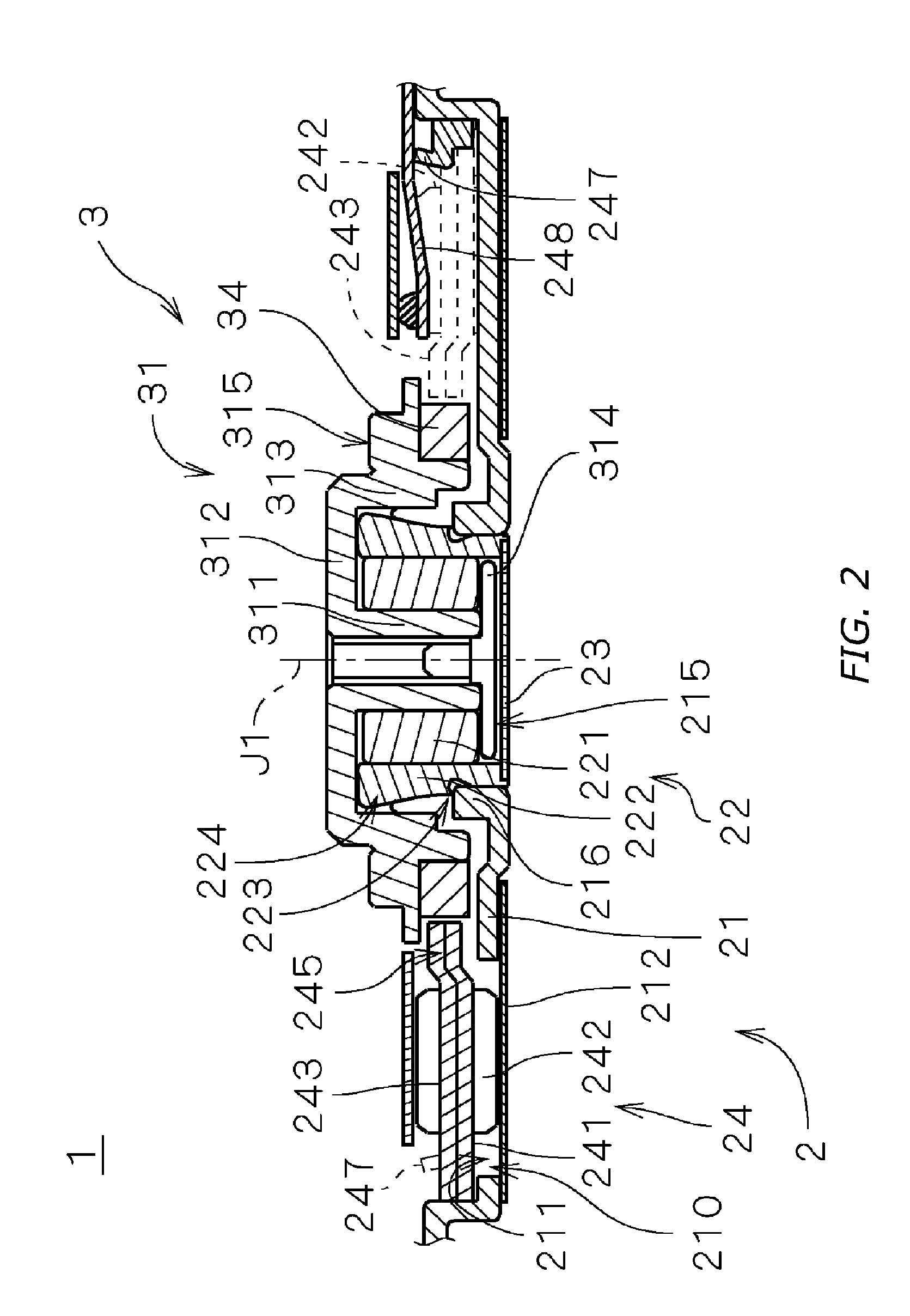
[0030]FIG. 1 is a drawing showing an internal structure of a recording disk driving device 60 including an electric spindle motor 1 (hereafter referred to as “motor 1”) according to a first embodiment of the invention. The recording disk driving device 60 is a hard disk device and includes: a disk-shaped recording disk 62 on which information is recorded; an access portion 63 for writing and / or reading information in and out of the recording disk 62; the electric motor 1 for retaining and rotating the recording disk 62; and a housing 61 for housing the recording disk 62, the access portion 63, and the motor 1 in an internal space 110.
[0031]As shown in FIG. 1, the housing 61 includes a first housing member 611 and a plate-shaped second housing member 612. The first housing member 611 has an opening at its upper portion and an inner bottom face, and the motor 1 and the access portion 63 are mounted to the inner bottom face. The second housing member covers the opening of the first hou...
second embodiment
[0069]Next, a motor unit according to a second embodiment of the invention will be described. FIG. 9 is an enlarged vertical sectional view of a part of a motor 1a of the motor unit according to the second embodiment. As shown in FIG. 9, in the motor 1a, a raised portion 217a provided to a lower side of the stationary portion 2 locates in a different position from that in the motor 1 shown in FIG. 5. Other structures are similar to those in FIGS. 2 to 5 and are provided with the same reference numerals in the following description.
[0070]In the motor 1a, a lower end portion of the sleeve unit 22 is formed as the raised portion 217a protruding from surrounding portions on the lower side of the stationary portion 2. In other words, the sleeve unit 22 which is a member fixed to a center position of the base plate 21 includes the raised portion 217a. A raised face 2171 of the raised portion 217a is perpendicular to the central axis J1 and is formed in an annular shape around the central ...
third embodiment
[0081]Next, a motor unit according to a third embodiment of the invention will be described. FIG. 10 is an enlarged vertical sectional view of a part of a motor 1b of the motor unit according to the third embodiment. As shown in FIG. 10, a portion of the base plate 21 including a lower end portion of the sleeve mounting portion 216 (i.e., a portion closer to the central axis J1 than an inner edge of the annular sticker member 212), a lower end portion of the sleeve housing 222 of the sleeve unit 22, and the seal cap 23 are a raised portion 217b provided to the lower side of the stationary portion 2.
[0082]The raised face 2171 of the raised portion 217b is perpendicular to the central axis J1, formed in a circular shape around the central axis J1, and protrudes lower than the surface 2121 of the sticker member 212 stuck around the raised portion 217b as shown in FIG. 10. A distance D3 for which the raised portion 217b protrudes from the surface 2121 of the sticker member 212 in the di...
PUM
| Property | Measurement | Unit |
|---|---|---|
| thickness | aaaaa | aaaaa |
| thickness | aaaaa | aaaaa |
| thickness | aaaaa | aaaaa |
Abstract
Description
Claims
Application Information