Heat and moisture exchange device for respiratory therapy

a technology of heat exchange device and airway, which is applied in the direction of breathing mask, breathing protection, other medical devices, etc., can solve the problems of inadvertent tubing disconnect, affecting patient ventilation, and rotating pipes

Active Publication Date: 2009-09-29
TELEFLEX MEDICAL INC
View PDF40 Cites 29 Cited by
  • Summary
  • Abstract
  • Description
  • Claims
  • Application Information

AI Technical Summary

Problems solved by technology

However, operating the prior art device between HME and bypass functions requires rotation of the housing portions causing rotation of the pipes at each end of the housing portions.
Such housing and pipe rotation is transferred to the attached patient circuit tubing resulting in disturbing or loosening the pipe connections and contributes to inadvertent tubing disconnects affecting patient ventilation or necessitates repositioning of the patient ventilator circuit to relieve the added torque along the tubing.

Method used


Image

  • Heat and moisture exchange device for respiratory therapy
  • Heat and moisture exchange device for respiratory therapy
  • Heat and moisture exchange device for respiratory therapy

Examples


Embodiment Construction

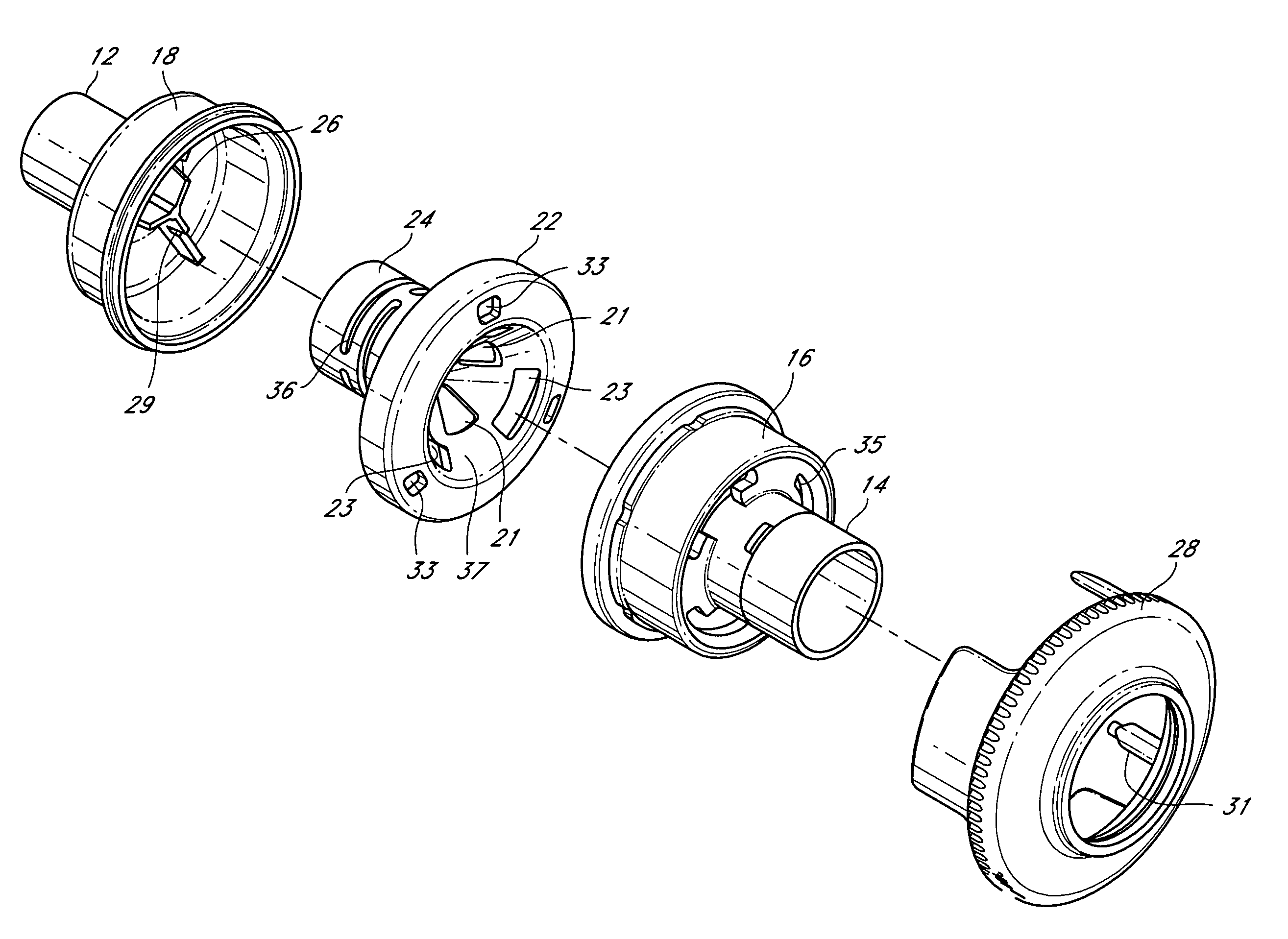
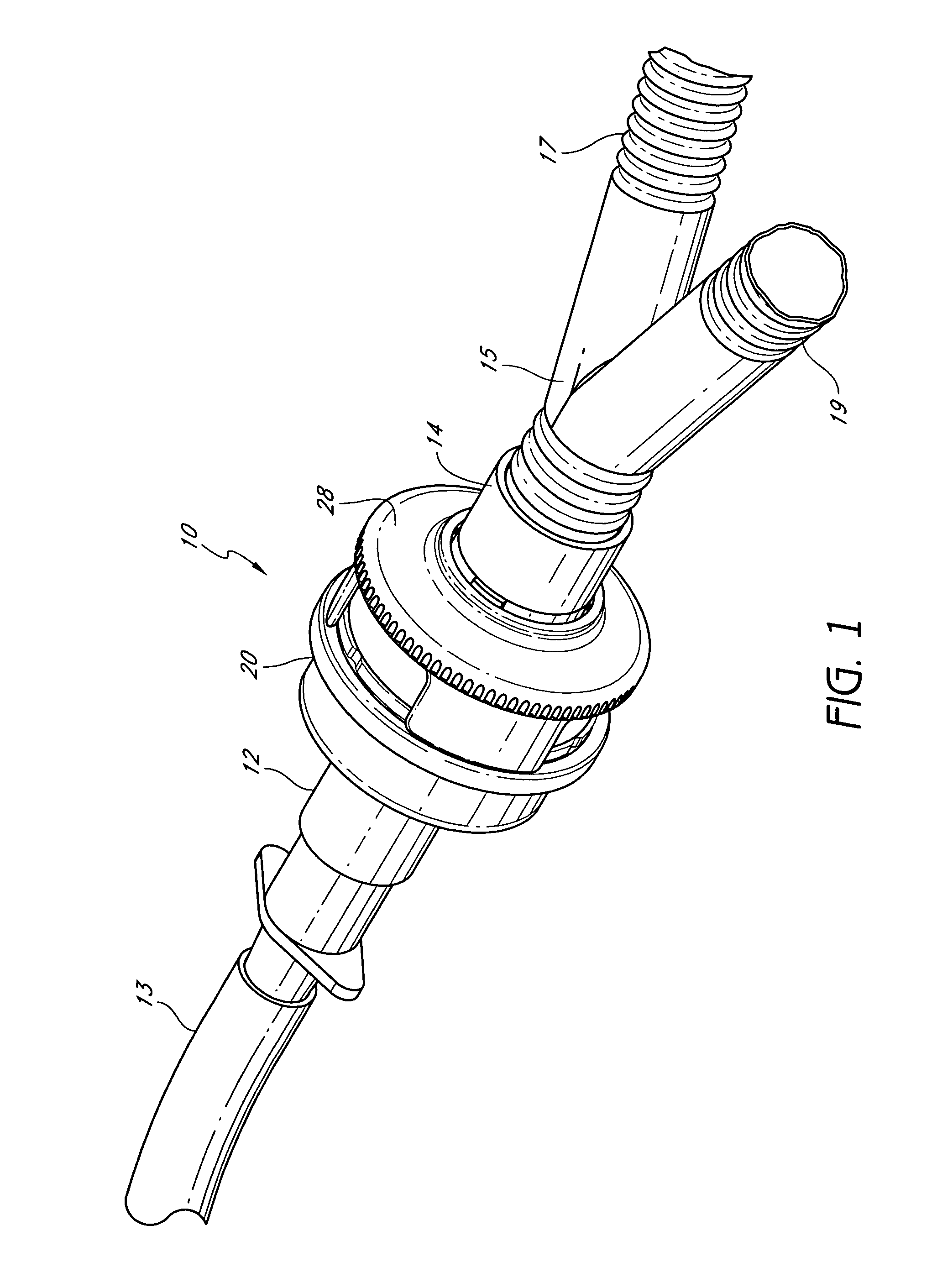
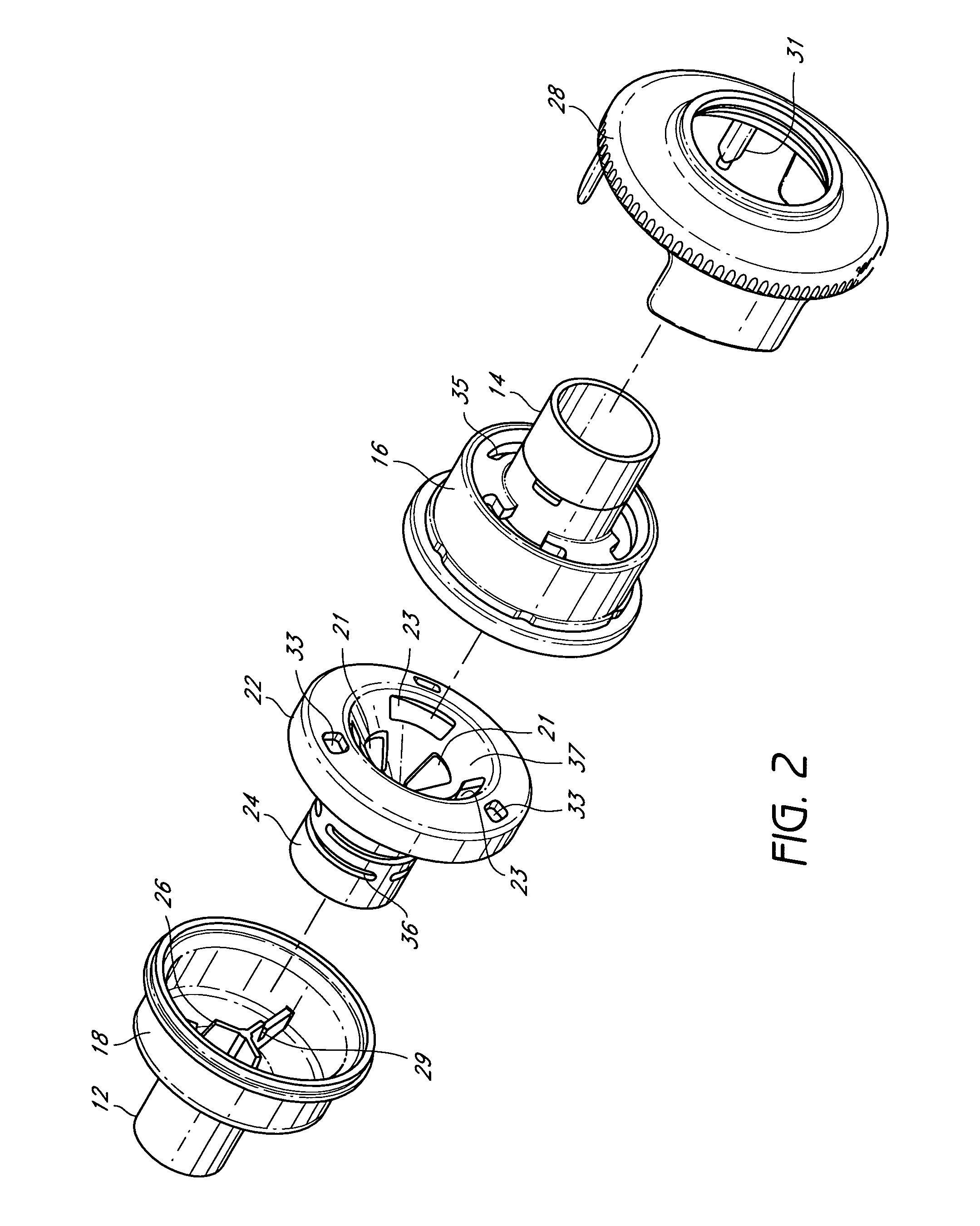
[0011]FIG. 1 shows an exterior view of the heat and moisture exchange device (HME) 10 with housing wall 20 having pipes 12 and 14 secured on the housing at opposite ends. Proximal end pipe 12 is secured to a tracheal tube 13 or to an endotracheal tube or other patient airway interface. At the opposite end of the housing is distal end pipe 14 to which is secured a ventilator circuit wye 15 and tubing assembly including inspiratory and expiratory circuit tubes 17 and 19. Such respiratory or ventilator circuit tubing and assemblies and patient gas delivery tubing, such as tracheal tube or endotracheal tubes or other patient gas delivery tubes, are not a part of the heat and moisture exchange device, are well understood by those skilled in the art and will not be described in further detail. Also shown is a valve selector 28 rotatably mounted relatively to the housing adjacent to pipe 14. Other tubing configurations may be secured to respective ends of the HME device. The tubing assembl...


PUM


Abstract

A heat and moisture exchange device for being selectively operated between HME mode and bypass mode comprises a rotatable valve and valve selector configured to be rotated without transferring rotational movement to tubing attached to the device.

Description

BACKGROUND OF THE INVENTION[0001]Heat and moisture exchange devices are often used to provide moisture to gases from a ventilator for respiratory therapy. To this end, a heat-moisture exchanger (HME) is positioned in the respiratory circuit, such a device containing a material or composition capable of absorbing heat / moisture from patient exhaled gas and desorbing the heat / moisture into the cool / dry respiratory gas stream from the ventilator for patient inhalation.[0002]For treating some respiratory conditions, it is desirable to introduce an aerosol generated by a nebulizer to the gas delivered to a patient. When such treatment is provided, it is desirable to bypass the HME to avoid absorption of the aerosol in the HME material. To avoid the inconvenience and inefficiency of removing the HME device each time aerosol treatment is to be administered, HME bypass devices have been designed, such as described in U.S. Patent Application Publication No. 2004 / 0084046. However, operating th...

Claims


Application Information

Patent Timeline
Patent Type & Authority Patents(United States)
IPC IPC(8): A62B18/08A62B9/02F28F27/02
CPCA61M16/1045A61M15/00A61M16/0465A61M2205/7563A61M16/20A61M16/0816A61M16/0833
Inventor BURK, MARC ALAN
Owner TELEFLEX MEDICAL INC
Why Eureka
Try Eureka