Chain reel for tillage implement

a chain reel and tillage implement technology, applied in agricultural rollers, agricultural tools and machines, agriculture, etc., can solve the problems of affecting the ability of the reel to perform the intended finishing operation, and requiring costly and frustrating downtime. , to achieve the effect of reducing the size of the clod, the surface soil clod

Active Publication Date: 2009-09-29
KUHN KRAUSE
View PDF11 Cites 25 Cited by
  • Summary
  • Abstract
  • Description
  • Claims
  • Application Information

AI Technical Summary

Benefits of technology

[0005]Accordingly, one important object of the present invention is to provide a tillage reel that is effective in reducing surface soil clods to the desired particle size while resisting the tendency to become packed with mud and trash materials during use in adverse conditions. Another important object of the invention is to provide a reel that is especially suited for use in strip till operations in which it is desirable to reduce clod size and pulverize the soil without destroying the integrity of the berm created by components that precede the reel.

Problems solved by technology

However, in these strip till operations, and in conventional field finishing operations as well, there is a tendency for the reels to ball up and plug as wet stick soil pushes past the reel bars into the interior of the reel.
This adversely affects the ability of the reel to perform its intended finishing operations and may necessitate costly and frustrating down time in order to clean out the plugged reel so that it will perform properly.

Method used


Image

  • Chain reel for tillage implement
  • Chain reel for tillage implement
  • Chain reel for tillage implement

Examples


Embodiment Construction

[0013]The present invention is susceptible of embodiment in many different forms. While the drawings illustrate and the specification describes certain preferred embodiments of the invention, it is to be understood that such disclosure is by way of example only. There is no intent to limit the principles of the present invention to the particular disclosed embodiments.

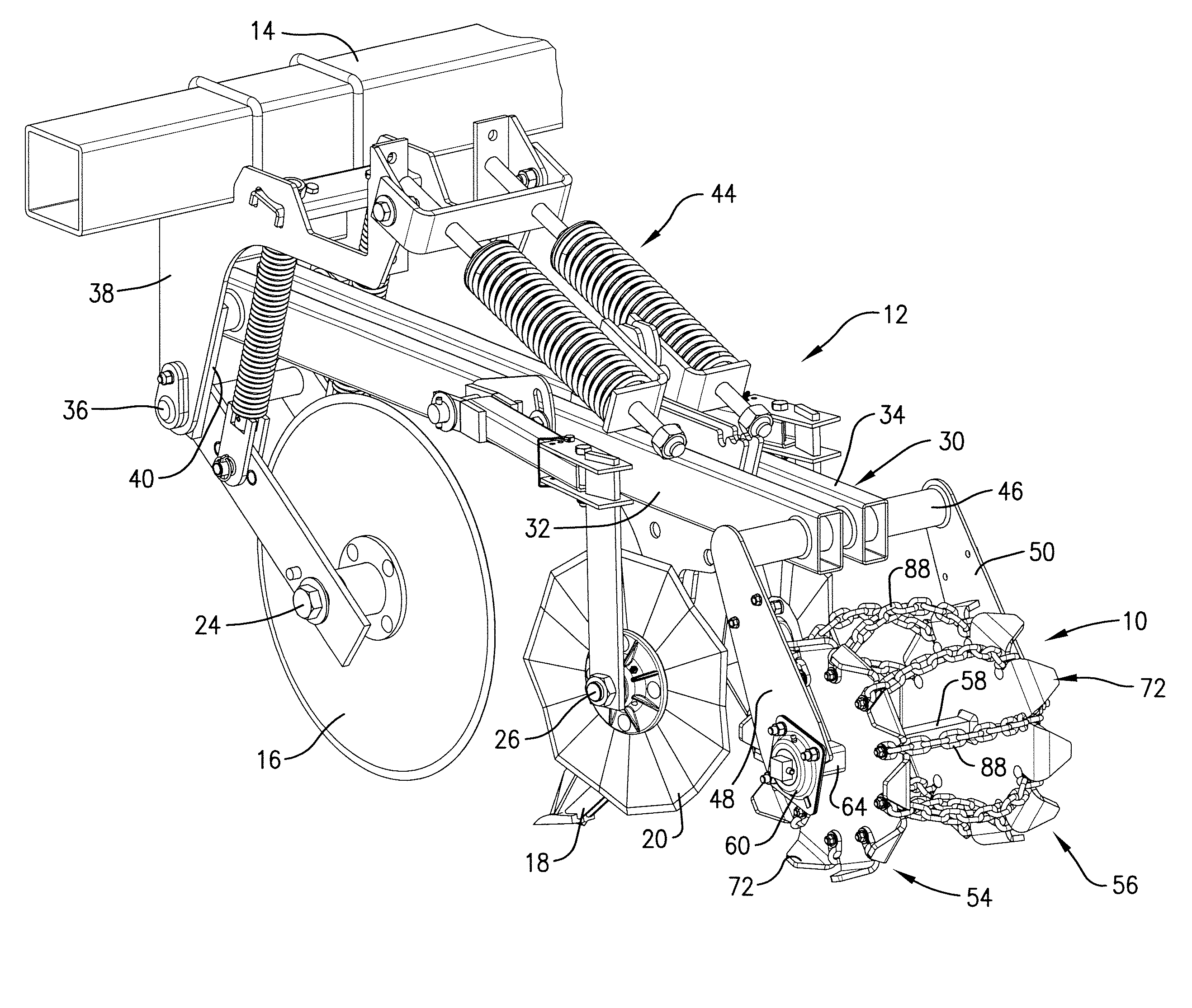
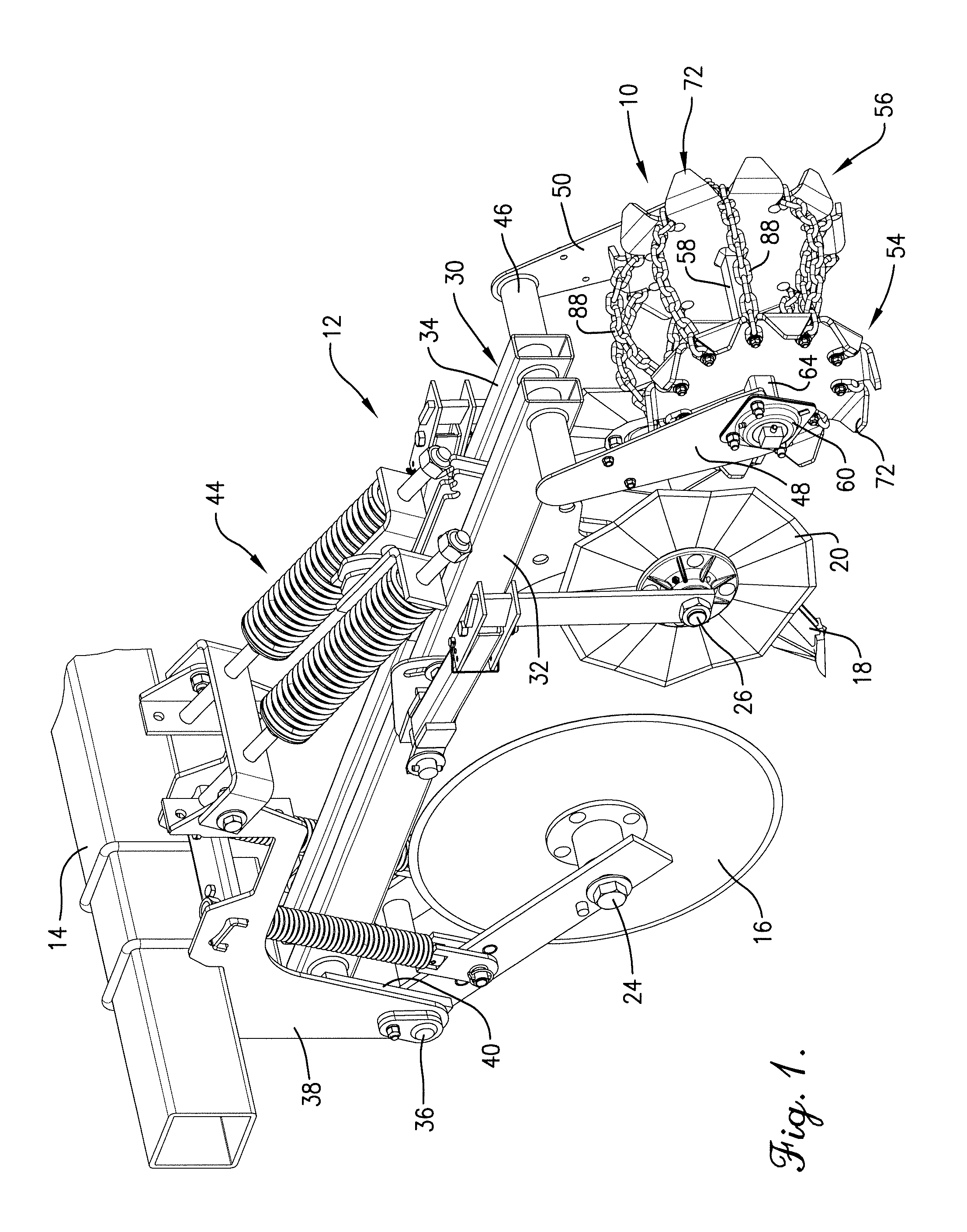
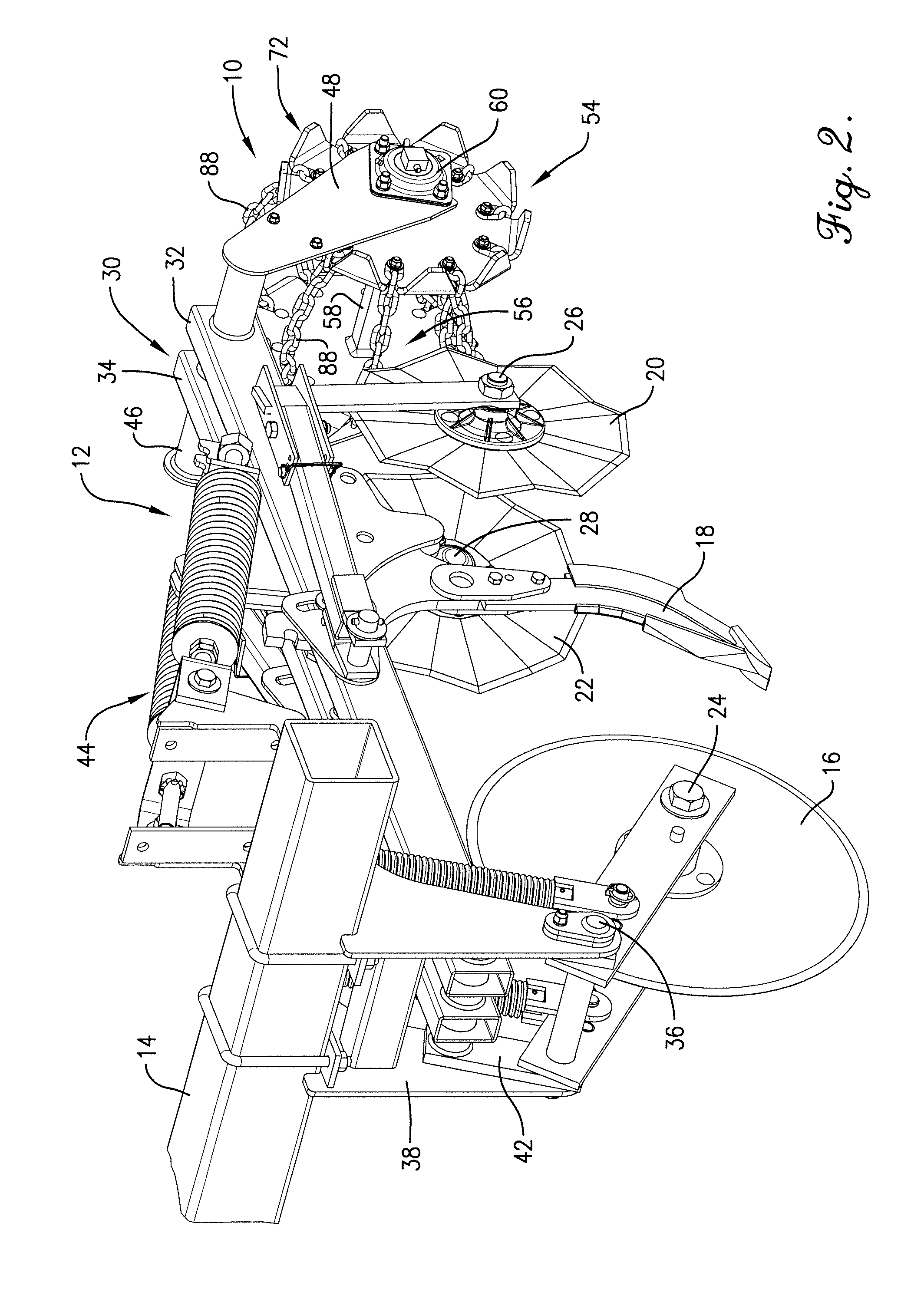
[0014]The tillage reel 10 in FIG. 1 is illustrated for purposes of example as part of a strip till row unit 12 which is, itself, one of a number of such units that collectively comprise a larger machine. Row unit 12 is mounted at its front end to a transversely extending tool bar 14 which, in turn, can be mounted to the three point hitch of a tractor (not shown) or serve as part of the frame of a pull-type piece of equipment. The principles of the present inventions are not limited to the type of equipment of which it is used although, as will be seen, reel 10 has particular utility for use as part of a strip till unit...


PUM


Abstract

In lieu of rigid bars, a tillage reel utilizes a number of elongated flexible elements such as lengths of link chain that are spaced circumferentially around the reel and extend axially thereof. The flexible elements bow outwardly by centrifugal force as the reel rolls along the ground during tillage operations to impact and fracture clods encountered at the lower front extremity of the reel. When the reel is used in connection with strip till operations, the flexible elements bow upwardly and inwardly along the lower periphery of the reel as they engage and conform to the transverse cross-section of the strip till berm, thereby avoiding destruction of the berm notwithstanding the clod-pulverizing action provided by the flexible elements.

Description

RELATED APPLICATION[0001]The present application is a non-provisional patent application and claims the priority benefit, with regard to all common subject matter, of earlier-filed U.S. provisional patent application Ser. No. 60 / 896,695, filed Mar. 23, 2007 and titled “CHAIN REEL FOR TILLAGE IMPLEMENT.” The identified earlier-filed application is hereby incorporated by reference in its entirety into the present application.TECHNICAL FIELD[0002]The present application relates to tillage tools and, more particularly, to a special ground-engaging tillage reel useful in breaking up surface clods and pulverizing the soil such as when preparing a seed bed.BACKGROUND AND SUMMARY[0003]Tillage reels are well known in the art and have typically been used in field finishing operations to reduce clod size and smooth the surface of the ground to prepare a suitable seed bed. Conventional reels are typically provided with a cage-like construction comprising two or more axially spaced bulkheads or ...

Claims


Application Information

Patent Timeline
Patent Type & Authority Patents(United States)
IPC IPC(8): A01B13/02
CPCA01B35/16A01B29/06
Inventor ANKENMAN, THOMAS W.
Owner KUHN KRAUSE
Why Eureka
Try Eureka