Biplane X-ray system

a x-ray system and plane technology, applied in the field of plane x-ray systems, can solve the problems of not being able to change the so-called isocenter of the x-ray c-arm, restricting the movement options, and not being able to record all image combinations

Inactive Publication Date: 2009-09-29
SIEMENS HEALTHCARE GMBH
View PDF8 Cites 24 Cited by
  • Summary
  • Abstract
  • Description
  • Claims
  • Application Information

AI Technical Summary

Benefits of technology

[0008]The present invention now also uses robots with biplane X-ray systems. The use of robots, such as, for example, (6-axis) buckling arm robots, provides greatly increased flexibility in the possible movements. There are more degrees of freedom, for example the isocenter is now also variable with biplane X-ray systems so that inter alia the working height is adjustable.
[0013]However, for special adaptation to the spatial conditions, the X-ray imaging device arranged on the ceiling can also comprise a first robot arm to which the X-ray radiation source is attached and a second robot arm to which the X-ray detector is attached. Dispensing with an X-ray C-arm enables additional flexibility to be obtained. The robot arms can in particular, for example, be embodied with the provision of a suitable joint so that they permit the folding upward of the X-ray radiation source and X-ray detector in the direction of ceiling (or onto the ceiling). The use of the two separate robot arms also makes it possible to embody them so they can move relative to each other. The rotation of the whole entity is not excluded. On the contrary, it is possible for the robot arms to be suspended from a rotatable plate. The plate can also be tiltable so that an additional degree of freedom is obtained which is not known with conventional stands with an X-ray C-arm. The X-ray radiation source and X-ray detector can also each be tiltable on their robot arm, in particular by the provision of a suitable joint at the respective end of the robot arms.
[0015]All the aforementioned embodiments, in which both X-ray imaging devices have a robot, have the advantage that they then do not necessarily have to work together within a biplane X-ray system. On the contrary, it is conceivable for the two X-ray imaging devices to be used simultaneously independently of each other as monoplane systems. In the case of conventional biplane X-ray systems, only one of the X-ray imaging devices, namely usually the floor-standing X-ray C-arm system can be used as a monoplane system, while the X-ray C-arm stand is merely moved away and cannot be used separately.
[0016]Particularly high flexibility is obtained with the embodiment with robots, to which an X-ray C-arm is attached, if said arm can be removed. The robots can then also be used for other tasks. For example, it can be provided that the X-ray radiation source can be attached to one robot and the X-ray detector to the other robot and these two robots can then be moved in coordination. In this way, a particularly highly flexible monoplane system can be provided on the basis of the two robots provided for the biplane X-ray system.
[0017]It can also be provided that one of the robots retains the X-ray C-arm and that the second robot is coupled to a patient table unit for moving the patient table. The robots can then be moved in coordination and the additional degrees of freedom in comparison to a conventional monoplane system, which are associated with the mobility of the patient table, can result in completely new possibilities for the utilization of the system.

Problems solved by technology

The mechanics of the X-ray C-arm system on the one hand and the fact that the second X-ray C-arm is arranged on a ceiling stand result in restricted movement options.
This means that it is not possible to record all image combinations.
With the previous systems, for example, it is not possible to change the so-called isocenter of the X-ray C-arm.
It is not possible to travel along scanning paths which satisfy a so-called completeness condition.

Method used


Image

  • Biplane X-ray system
  • Biplane X-ray system
  • Biplane X-ray system

Examples


Embodiment Construction

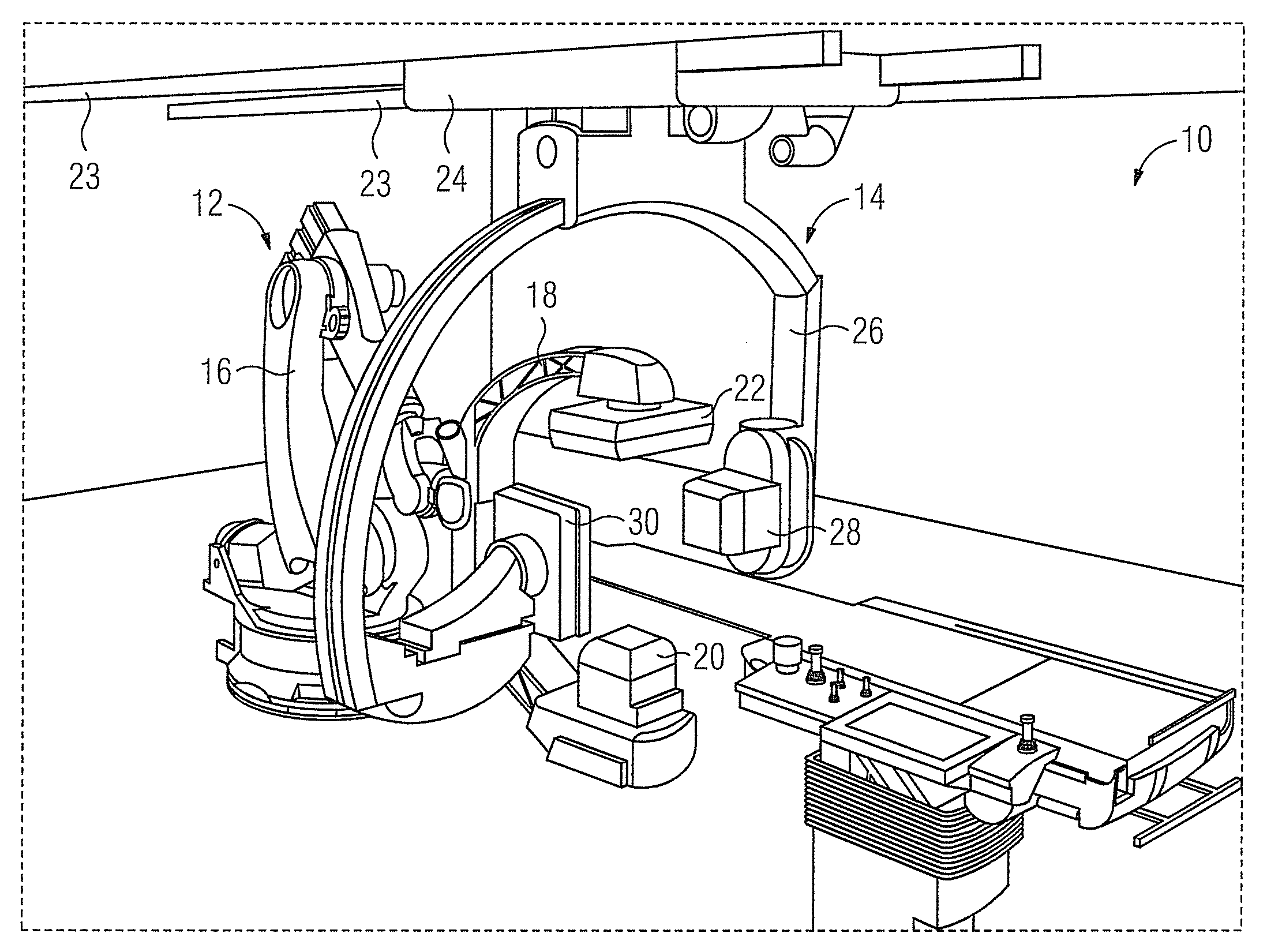
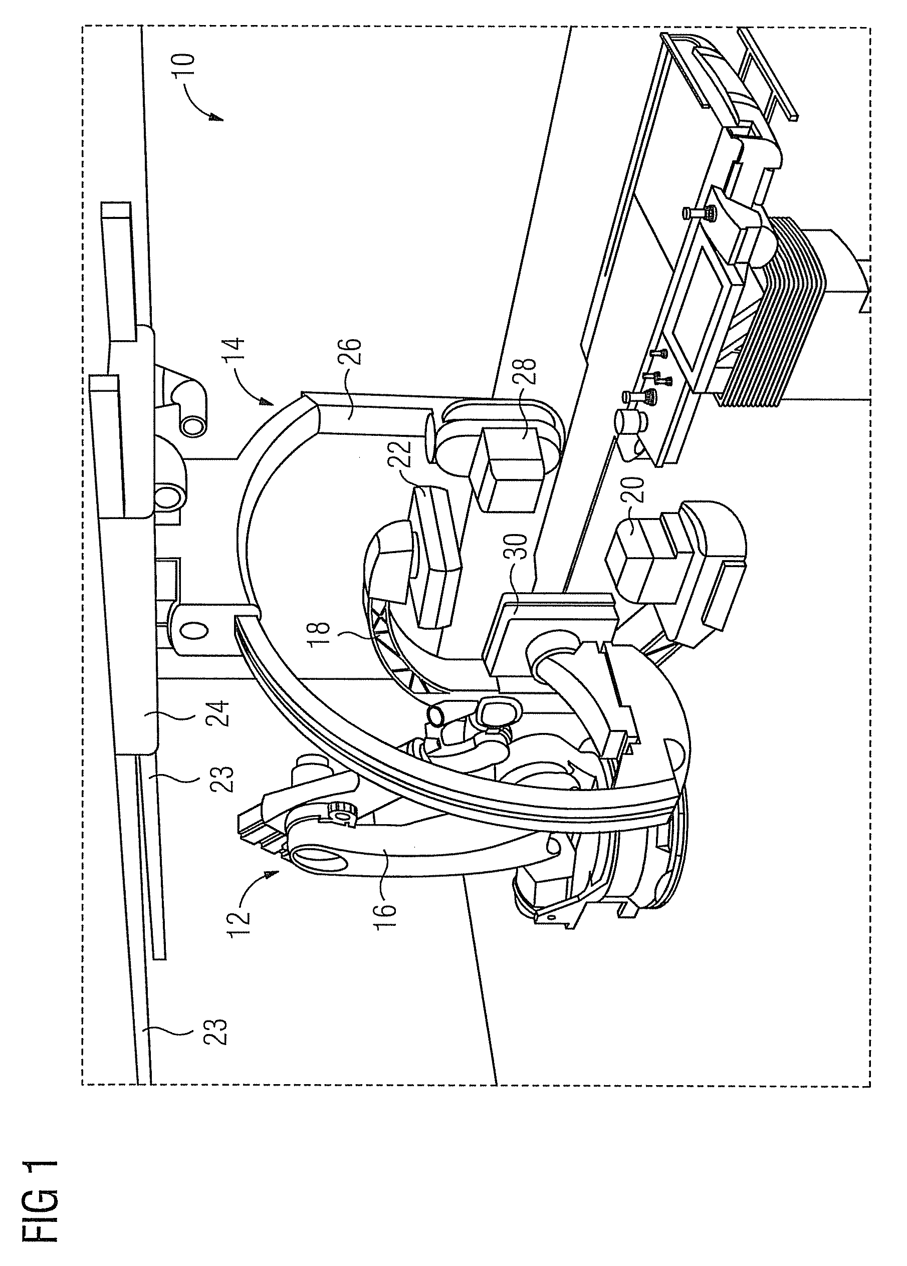
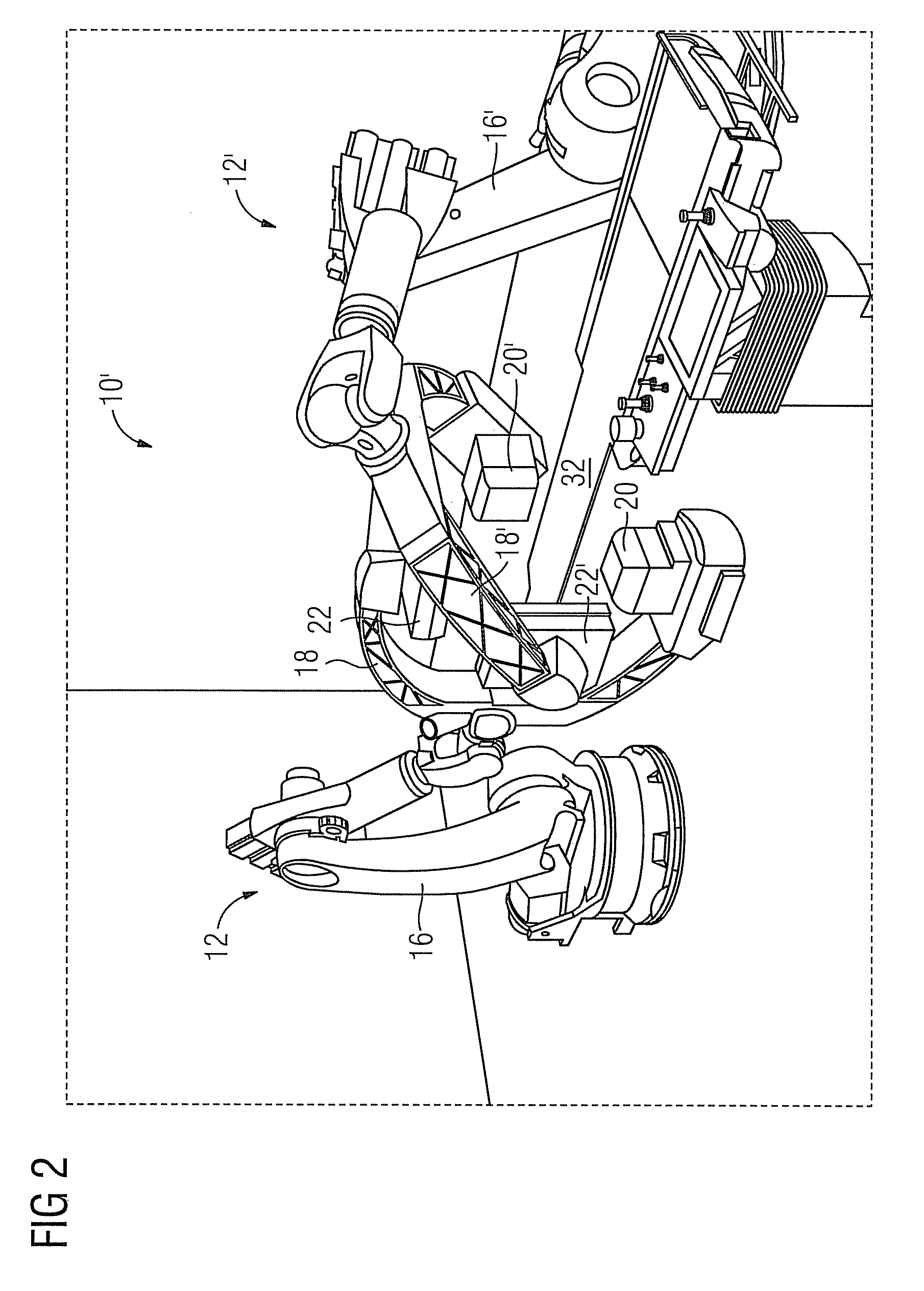
[0024]A biplane X-ray system shown in FIG. 1, designated 10 overall, comprises a first X-ray imaging device 12 and a second X-ray imaging device 14. The first X-ray imaging device 12 comprises a 6-axis buckling arm robot 16, to which is attached a C-arm 18, which bears an X-ray source 20 and an X-ray detector 22. The second X-ray imaging device 14 is a conventional X-ray imaging device comprising a stand 24 which can be moved on rails 23 supporting a movable X-ray C-arm 26 to which an X-ray radiation source 28 and an X-ray detector 30 are also attached. The biplane X-ray system 10 differs from conventional biplane X-ray systems in the use of the robot 16. The robot 16 has many more degrees of freedom than a conventional X-ray C-arm system. This makes certain positions of the X-ray radiation source 20 and X-ray detector 22 possible, in particular also relative to the X-ray radiation source 28 and the X-ray detector 30, therefore, the imaging possibilities of the biplane X-ray system ...


PUM


Abstract

In a biplane X-ray system, a robot is used for moving at least a pair comprising an X-ray radiation source and an X-ray detector. The robot can be a buckling arm robot bearing an X-ray C-arm. It is also possible for the X-ray radiation source and X-ray detector each to be suspended from the ceiling of the room by means of robot arms.

Description

CROSS REFERENCE TO RELATED APPLICATIONS[0001]This application claims priority of German application No. 10 2007 033 716.9 filed Jul. 19, 2007, which is incorporated by reference herein in its entirety.FIELD OF THE INVENTION[0002]The invention relates to a biplane X-ray system. Biplane X-ray systems of this kind are known with two X-ray imaging devices each comprising an X-ray radiation source, an X-ray detector and means for moving the X-ray radiation source and X-ray detector.BACKGROUND OF THE INVENTION[0003]Until now, X-ray C-arms have been used with both X-ray imaging devices. The first X-ray imaging device is usually a conventional floor-based X-ray C-arm system and the second X-ray imaging device comprises a stand suspended from the ceiling with a pivotable X-ray C-arm. The ceiling stand is movable so that the first X-ray imaging device can also be used alone, that is as a monoplane system.[0004]When using a biplane X-ray system, two image planes are defined corresponding to th...

Claims


Application Information

Patent Timeline
Patent Type & Authority Patents(United States)
IPC IPC(8): H05G1/02
CPCA61B6/4014A61B6/4441A61B6/4458A61B6/4464
Inventor GREBNER, ALBERTKLINGENBECK-REGN, KLAUSLURZ, WINFRIEDSATTLER, STEFANSCHÖNBORN, MANFRED
Owner SIEMENS HEALTHCARE GMBH
Why Eureka
Try Eureka