
Device and method for reading a capacitive sensor, in particular of a micro-electromechanical type

a capacitive sensor and micro-electromechanical technology, applied in the field of micro-electromechanical type devices and methods, can solve the problem that the cds technique does not enable suppression of the low-frequency disturbance generated upstream of the charge amplifier

Active Publication Date: 2009-09-29
STMICROELECTRONICS SRL
View PDF17 Cites 69 Cited by
  • Summary
  • Abstract
  • Description
  • Claims
  • Application Information

AI Technical Summary

Benefits of technology

The present invention provides a device and method for reading a capacitive sensor that overcomes the drawbacks of existing methods. This makes it easier to use and more accurate.

Problems solved by technology

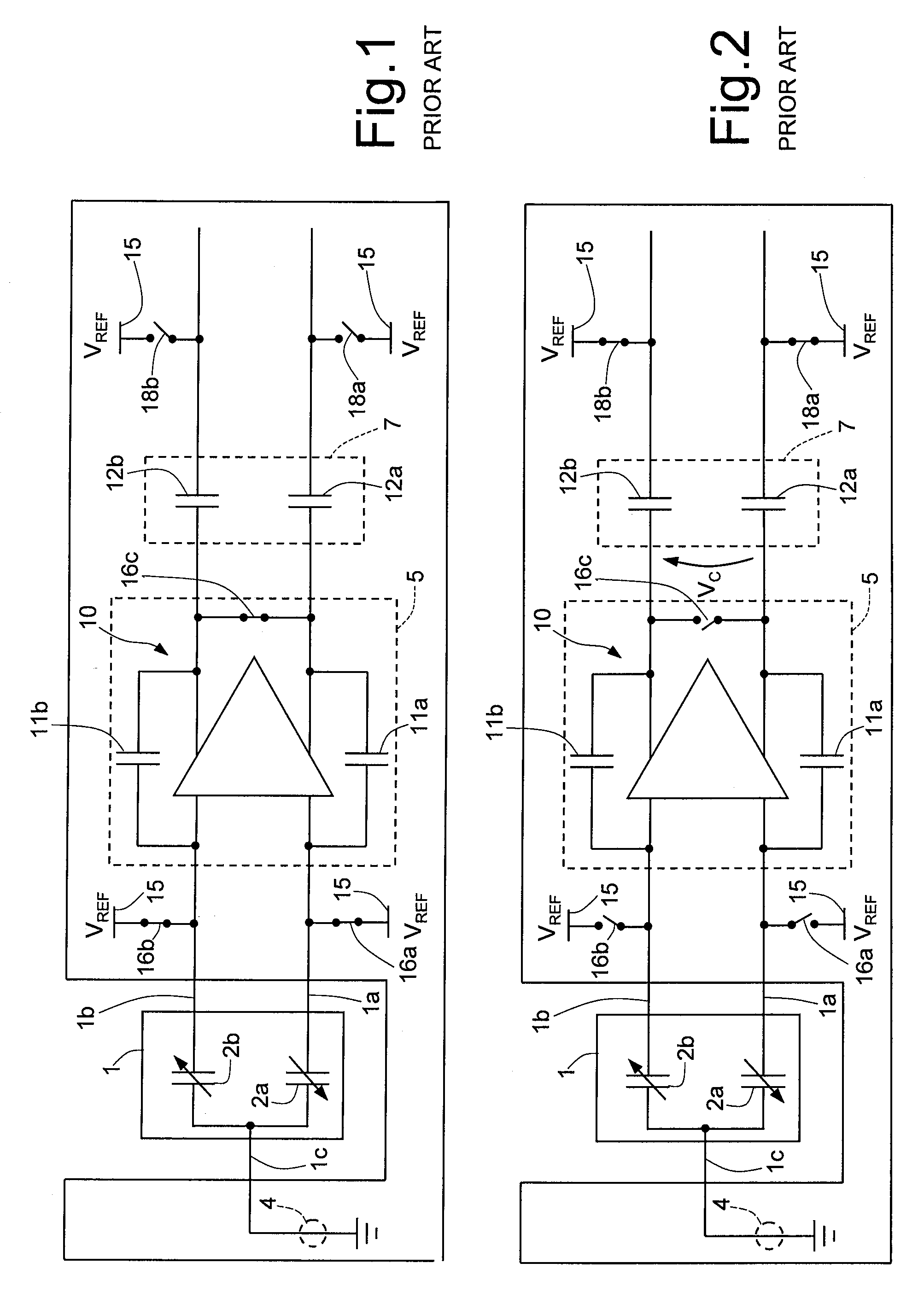
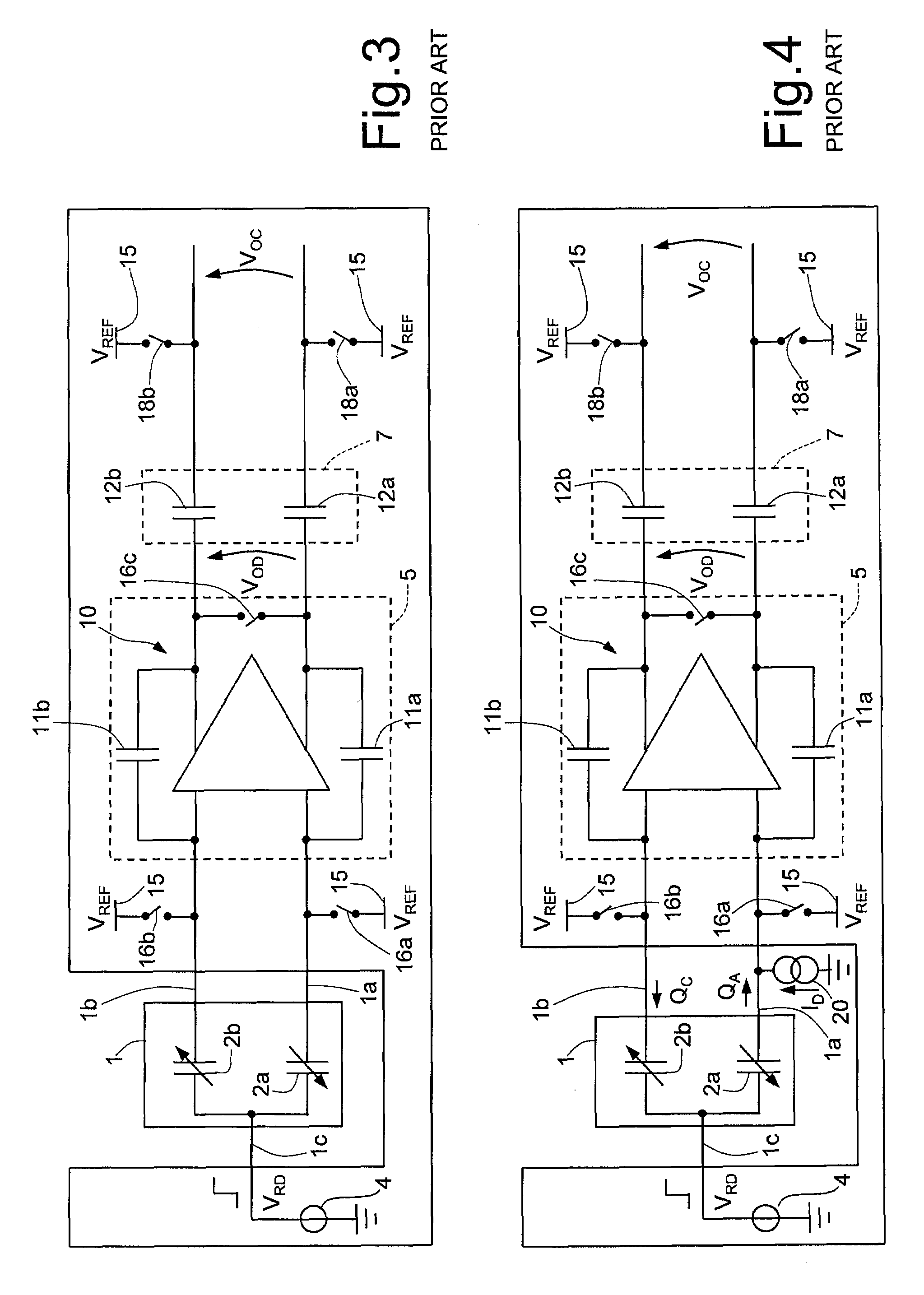
Albeit effective for eliminating the disturbance described, the CDS technique does not, however, enable suppression of the low-frequency disturbance generated upstream of the charge amplifier 10.
The problem, in addition, becomes increasingly more important because the need to reduce also the overall dimensions pushes in the direction of using as switches MOS transistors with very short channel, which suffer more from current leakages.
Other causes of disturbance are the inevitable thermal drifts and the ageing of the components, so that spurious resistive paths may be formed within the inertial sensor 1.

Method used


Image

  • Device and method for reading a capacitive sensor, in particular of a micro-electromechanical type
  • Device and method for reading a capacitive sensor, in particular of a micro-electromechanical type
  • Device and method for reading a capacitive sensor, in particular of a micro-electromechanical type

Examples


second embodiment

[0058]FIG. 10 shows the invention. In this case, an acceleration-detection apparatus 200 comprises an inertial sensor 201, of the differential capacitive MEMS type, as already described previously, and a read device 203, associated to the inertial sensor 201. The read device 203, which is of the discrete-time type, comprises a signal source 204, a modulator stage 205, a sensing stage 207, which in turn includes a charge-voltage converter 208, a canceling stage 209, a demodulator stage 210, and a phase-generator stage 213 substantially identical to the ones already described. Furthermore, the read device 203 includes a sigma-delta analog-to-digital converter of a low-pass type, more simply referred to as sigma-delta converter 212, which is connected downstream of the demodulator stage 210. In this case, the sigma-delta converter 212 advantageously also integrates the function of the low-pass filter and thus suppresses the effects of the disturbance current ID due to the dispersions u...

third embodiment

[0059]In accordance with the invention (illustrated in FIG. 11), an acceleration-detection apparatus 300 comprises an inertial sensor 301 of the differential capacitive MEMS type, as already described previously, and a read device 303, associated to the inertial sensor 301. The read device 303, of the discrete-time type, comprises a signal source 304, a modulator stage 305, a sensing stage 307, which in turn includes a charge-voltage converter 308, a canceling stage 309, a demodulator stage 310, and a phase-generator stage 313, substantially identical to the ones already described. Furthermore, the read device 303 comprises a sigma-delta converter 311 and a low-pass filter 312 of a numeric type, cascaded to one another downstream of the demodulator stage 310.

[0060]The output of the sigma-delta converter 312 generates a demodulated numeric acceleration signal A starting from the demodulated output voltage VOD, supplied by the demodulator stage 310. In the demodulated numeric accelera...


PUM


Abstract

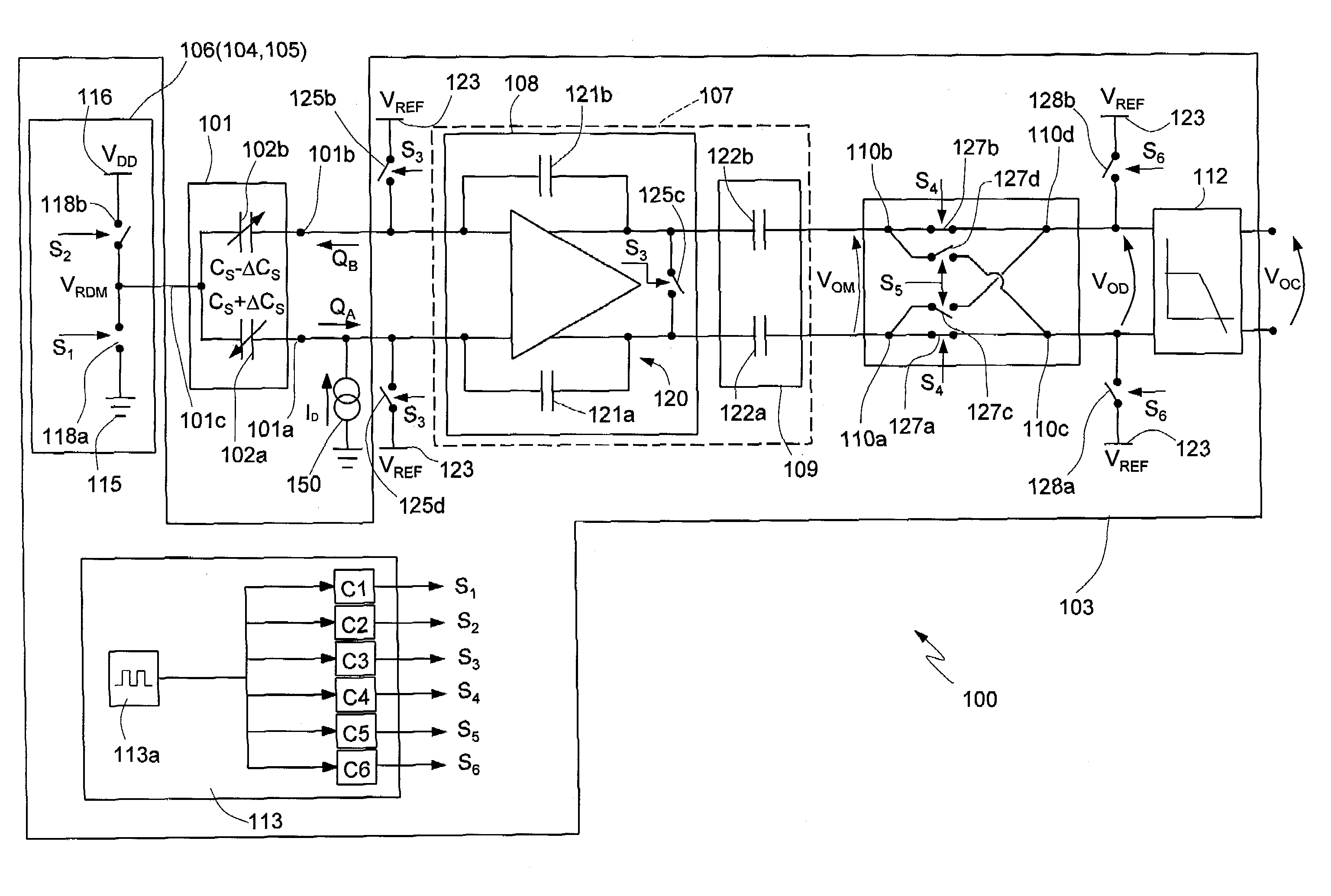
A read device of a capacitive sensor includes: a signal source supplying an electrical read signal for driving the capacitive sensor; and a discrete-time sense circuit for generating an electrical output signal, correlated to variations of capacitance of the capacitive sensor, in response to variations of the electrical read signal. The device moreover includes: a modulator stage for generating a modulated electrical read signal on the basis of the electrical read signal and supplying the modulated electrical read signal to the capacitive sensor; a demodulator stage, connected to the sense circuit, for demodulating the electrical output signal and generating a demodulated electrical output signal; and a low-pass filtering stage for generating a filtered electrical output signal, on the basis of the modulated electrical output signal.

Description

BACKGROUND OF THE INVENTION[0001]1 Field of the Invention[0002]The present invention relates to a device and to a method for reading a capacitive sensor, in particular of a micro-electromechanical type.[0003]2 Description of the Related Art[0004]As is known, the use of capacitive sensors is continuously spreading to numerous applications, in which the reduction of consumption is a fundamental target. For example, capacitive inertial micro-electromechanical-system (MEMS) sensors of a differential type are increasingly frequently used in a wide range of portable electronic devices, such as cell phones, palm-top computers, digital camcorders and cameras, and the like, which are supplied autonomously by batteries. Clearly, in cases of this sort the reduction of the consumption is indispensable for increasing the autonomy of the device.[0005]In order to minimize the power absorption, very frequently traditional continuous-time read circuits for capacitive sensors have been replaced by sw...

Claims


Application Information

Patent Timeline
Patent Type & Authority Patents(United States)
IPC IPC(8): G01R27/26H03F1/02
CPCG01P15/125
Inventor UNGARETTI, TOMMASOLASALANDRA, ERNESTO
Owner STMICROELECTRONICS SRL
Learn More