Image forming apparatus and method

a technology of image forming apparatus and forming apparatus, which is applied in the direction of printing apparatus, other printing apparatus, etc., can solve the problems of image loss glossiness, achieve the effects of preventing bleeding, reducing undulations on the print surface, and reducing the effect of bleeding, color mixing and the lik

Inactive Publication Date: 2009-10-06
FUJIFILM CORP
View PDF6 Cites 12 Cited by
  • Summary
  • Abstract
  • Description
  • Claims
  • Application Information

AI Technical Summary

Benefits of technology

[0009]The present invention has been contrived in view of such circumstances, an object thereof being to provide an image forming apparatus and method which can achieve high-quality image formation by controlling the viscosity of deposited ink in order to reduce interference between liquid droplets on the recording medium, movement of the liquid, feathering, and the like, and hence cause the droplets to become fixed reliably in a satisfactory dot configuration, as well as smoothing the printed surface.

Problems solved by technology

Moreover, there has been a problem in that when the ink hardens and fixes on the surface of a non-permeable recording medium (or a recording medium of low permeability), undulations remain on the printed surface (the surface of the ink) and the resulting image loses glossiness.

Method used


Image

  • Image forming apparatus and method
  • Image forming apparatus and method
  • Image forming apparatus and method

Examples


example 1

Control Method Example 1

[0148]If a medium having high porosity and rapid permeation is being used, or if the droplet ejection volume (droplet volume) is small, or if there is a combination of these circumstances, then the tendency of the control procedure is to delay the electric field switch-off timing (namely, to lengthen the period of T1), and to advance the UV light irradiation timing (namely, to shorten the period of T2).

example 2

Control Method Example 2

[0149]Conversely, if a medium having low porosity and slow permeation is being used, or if the droplet ejection volume (droplet volume) is large, or if there is a combination of these circumstances, then the tendency of the control procedure is to advance the electric field switch-off timing (namely, to shorten the period of T1), and to delay the UV light irradiation timing (namely, to lengthen the period of T2).

[0150]In FIG. 12, an example is illustrated in which UV light is irradiated after switching off the electric field (T12), but in implementing the present invention, it is also possible to adopt a control mode in which the irradiation of UV light is started while the electric field is still on, and the electric field switches off while the UV light is being irradiated (T1>T2).

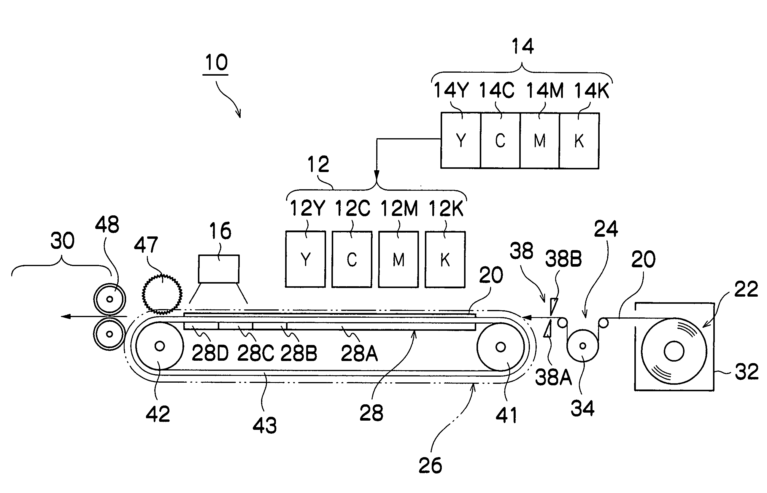
[0151]The embodiment described above related to a structural example in which an electrode unit 28 capable of controlling the area in which an electric field is generated is dispo...

further embodiment

[0155]FIG. 13 is a schematic drawing showing a further embodiment of the present invention, and FIG. 14 is a principal block diagram of same. In FIG. 13 and FIG. 14, items which are the same as or similar to those in FIG. 1 and FIG. 9 are labeled with the same reference numerals and description thereof is omitted here.

[0156]In the example in FIG. 13, the electrode unit 28 is constituted by a fixed zone (28A) only, and the area in which the electric field is generated does not change at all. On the other hand, the UV light source 16 is supported movably in the conveyance direction of the medium by means of a light source movement mechanism 170.

[0157]The device for moving the UV light source 16 is not limited in particular, but, for example, the light source movement mechanism 170 is constituted by a movable platform 172 to which the UV light source 16 is fixed, a guide member 174 for causing the movable platform 172 to travel in line with the medium conveyance direction, and a motor ...


PUM


Abstract

The image forming apparatus comprises: an ejection head which ejects ink having electrorheological properties onto a recording medium; an electric field application device which applies an electric field to a droplet of the ink deposited on the recording medium; a fixing promotion device which performs fixing promotion process for promoting fixing of the ink on the recording medium; and a timing control device which controls a time difference between an electric field application cessation timing at which an application of the electric field to the ink on the recording medium by the electric field application device is ceased and a fixing promotion process timing at which the fixing promotion process is performed by the fixing promotion device.

Description

BACKGROUND OF THE INVENTION[0001]1. Field of the Invention[0002]The present invention relates to an image forming apparatus and method, and more particularly, to image forming technology suitable for an image forming apparatus, such as an inkjet recording apparatus which forms images on a recording medium by ejecting liquid droplets from nozzles.[0003]2. Description of the Related Art[0004]In an inkjet recording head of a recording apparatus, it has been proposed to use an electrorheological fluid in order to prevent bleeding and color mixing of ink, and the like, on the recording medium (see Japanese Patent Application Publication Nos. 2-169253, 2-212149 and 5-4343).[0005]Japanese Patent Application Publication No. 2-169253 discloses an image forming material which is an electrorheological fluid in which a coloring material is dispersed or dissolved in an insulating solvent. Japanese Patent Application Publication No. 2-212149 discloses an image forming method in which an electrorh...

Claims


Application Information

Patent Timeline
Patent Type & Authority Patents(United States)
IPC IPC(8): B41J2/01
CPCB41J2/06
Inventor KONNO, MASAAKIKADOMATSU, TETSUZO
Owner FUJIFILM CORP
Why Eureka
Try Eureka