Color correcting contrast enhancement of displays

a contrast enhancement and color correction technology, applied in the direction of color television details, instruments, projectors, etc., can solve the problems of less ear image, negative impact on the image provided by the display, and diminish the visual presentation of the avionics display

Inactive Publication Date: 2009-10-06
HONEYWELL INT INC
View PDF21 Cites 87 Cited by
  • Summary
  • Abstract
  • Description
  • Claims
  • Application Information

AI Technical Summary

Problems solved by technology

Ambient light may negatively impact images provided by the displays by decreasing contrast which generally results in a less ear image.
For example, avionics displays provide a visual indication of in-bound terrain, aircraft status, or other flight information particularly for real-time decision-making, and ambient light may diminish the visual presentation of avionics displays.
In general, this approach is typically limited by the available brightness of the display.
For applications where the display is to be viewed in bright sunlight, it is often difficult or not practical to build a display that is sufficiently bright.
Further complicating projection display performance, limited types of light sources are available for projection displays.
Such light sources are generally not sufficiently spectrally balanced, particularly for avionics displays, and are classified a having fixed spectral output.
However, where a specific color requirement is needed for the display, these types of lamps may not be suitable.
For example, Mercury lamps tend to be deficient in red light while providing ample blue and green light.
These reductions in efficiency due to chromaticity adjustment and ambient contrast enhancement may be problematic in applications such as avionics displays, where more stringent requirements are often placed on luminance, power, and other related requirements as well.

Method used


Image

  • Color correcting contrast enhancement of displays
  • Color correcting contrast enhancement of displays
  • Color correcting contrast enhancement of displays

Examples


Embodiment Construction

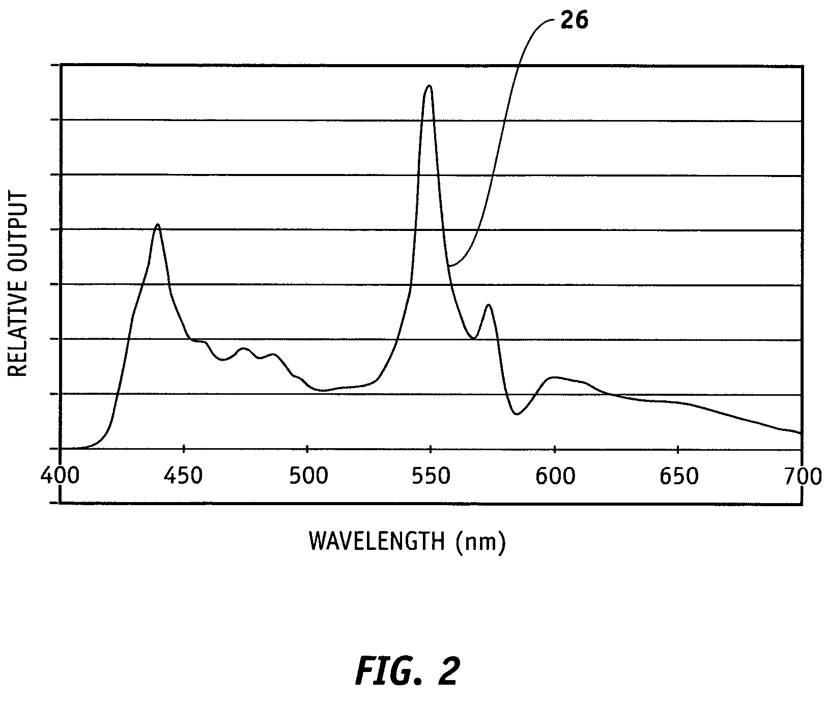
[0020]The following detailed description of the invention is merely exemplary in nature and is not intended to limit the invention or the application and uses of the invention. Furthermore, there is no intention to be bound by any theory presented in the preceding background of the invention or the following detailed description of the invention.

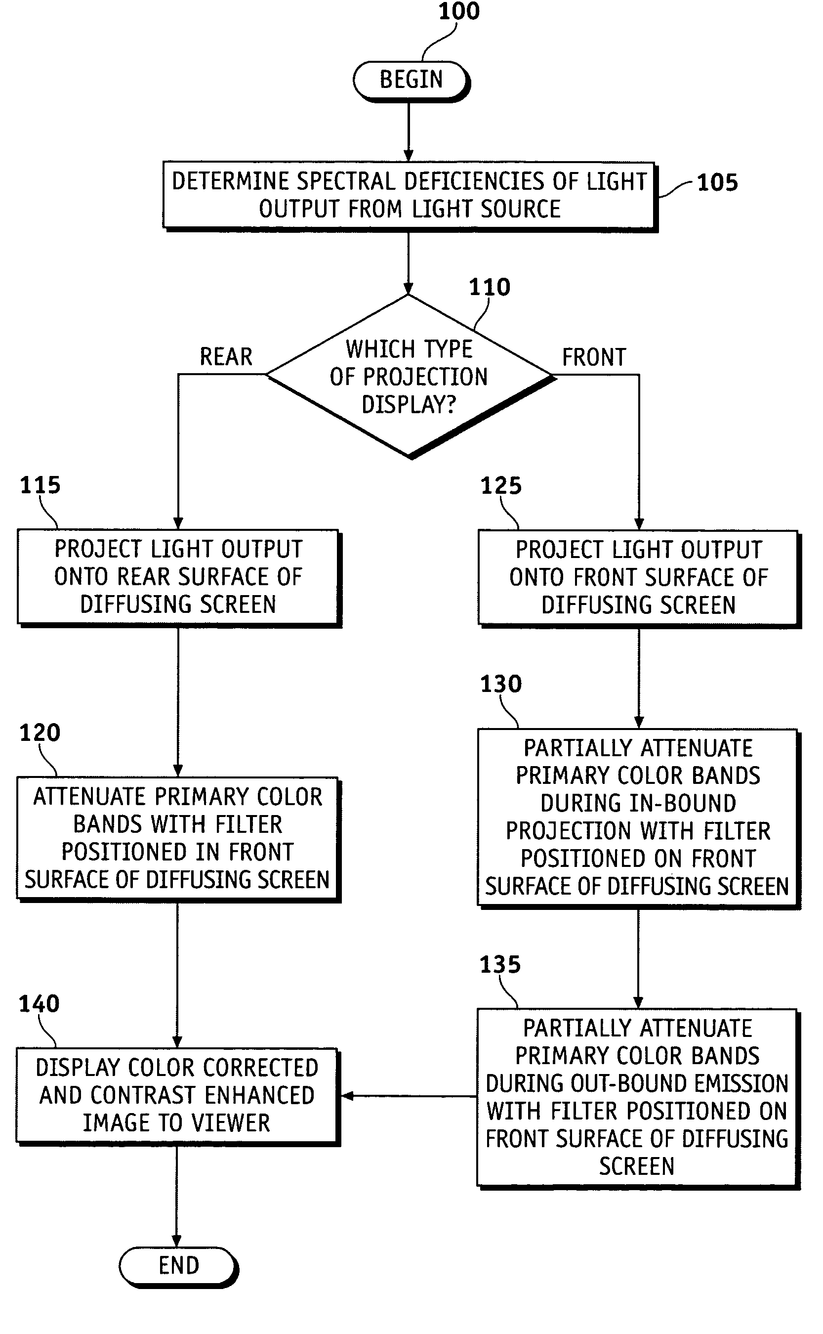
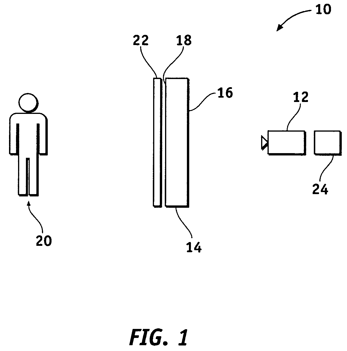
[0021]According to various exemplary embodiments, a display system includes a color correction contrast enhancement filter to provide contrast enhancement of displayed images particularly useful in high ambient light conditions. The filter is preferably located at an image output of the display system, such as a display screen or diffusing screen. The display system may include a variety of displays including but not limited to rear projection displays, front projection displays, and other conventional image displays. Although the display system is described hereinbelow with respect to projection displays for convenience of explanation, a va...


PUM


Abstract

Methods and apparatus are provided for color correction and contrast enhancement of projection displays. A visual display system includes a projector having a light source with a fixed spectral output, a display screen receiving the output of the projector and emitting a diffused output, and a color correction contrast enhancement filter positioned between the diffusing screen and a viewer. The filter differentially attenuates primary colors of the emission from the diffusing screen. The method includes projecting a light output from a light source having a fixed spectral output onto a diffusing screen, and attenuating primary colors of the emission from the diffusing screen with a light filter positioned adjacent to the diffusing screen.

Description

FIELD OF THE INVENTION[0001]The present invention generally relates to spectrally balancing color displays, and more particularly relates to color correction and contrast enhancement of projection displays.BACKGROUND OF THE INVENTION[0002]Projection displays have numerous home and commercial applications. For example, rear-projection television displays are gaining market share for home use. Displays have also been important as information-conveying devices, such as those used in aircraft to provide terrain or flight information data. Ambient light may negatively impact images provided by the displays by decreasing contrast which generally results in a less ear image. The impact of ambient light is more significant in display applications where acquisition of information from the display is particularly important. For example, avionics displays provide a visual indication of in-bound terrain, aircraft status, or other flight information particularly for real-time decision-making, an...

Claims


Application Information

Patent Timeline
Patent Type & Authority Patents(United States)
IPC IPC(8): G03B21/14
CPCG03B21/62H04N9/3197H04N9/3158G02F2001/133618G02B5/20G02F1/133618H04N9/3182
Inventor LARSON, BRENT D.DUBIN, MATTHEW B.
Owner HONEYWELL INT INC
Why Eureka
Try Eureka