Insert type cutting instrument and insert, method for attaching insert to insert main body

a cutting instrument and insert-type technology, applied in the direction of metal-working equipment, milling equipment, metal-working apparatus, etc., can solve the problems of insert damage, insert position relationship between the two through-holes may get out of imperceptible order, and the insert-type cutting device can not be used in the cutting field. reduce the cutting resistance of the insert-type cutting device, improve the separation of chips from the insert, and prevent the effect of insert displacemen

Active Publication Date: 2009-10-06
MITSUBISHI MATERIALS CORP
View PDF38 Cites 15 Cited by
  • Summary
  • Abstract
  • Description
  • Claims
  • Application Information

AI Technical Summary

Benefits of technology

[0022]Further, in the condition that the insert is mounted on the insert seat, the second screw hole of the insert seat is located closer to the tip of the instrument main body than the first screw hole, and the second through-hole of the insert is located closer to the tip of the instrument main body than the first through-hole. Also, the center of the second screw hole of the insert seat is located closer to the axis of the instrument main body than the center of the second through-hole of the insert, and is located closer to the base end of the instrument main body than the center of the second through-hole. Then, the second clamping screw is tightly screwed into the second screw hole, and thereby the insert is pushed toward the base end of the instrument main body, and is pushed toward the base end of the instrument main body. Therefore, the insert is attached to the instrument main body. As a result, if the distance between the two through-holes is shorter than its order, it is possible to prevent the insert from pushing toward the tip of the instrument main body by the second clamping screw located close to the tip of the instrument main body. Therefore, the insert can be reliably attached to the instrument main body.
[0030]As mentioned above, according to the present invention, it is possible to provide an insert type cutting instrument which enables tight attachment of an insert so as not to move by the centrifugal force while the instrument main body is high-speed rotated, and it is possible to provide the insert included in this insert type cutting instrument.

Problems solved by technology

If the insert is displaced, it is impossible to perform cutting with high accuracy, and the insert may become damaged due to cutting resistance.
Further, a positional relationship between the two through-holes may get out of imperceptibly order due to a dispersion of the accuracy with cutting the two through-holes in the insert.
As a result, a cutting accuracy by the insert type cutting instrument may deteriorate by a displacement of the insert caused by the centrifugal force, and the insert may become damaged.

Method used


Image

  • Insert type cutting instrument and insert, method for attaching insert to insert main body
  • Insert type cutting instrument and insert, method for attaching insert to insert main body
  • Insert type cutting instrument and insert, method for attaching insert to insert main body

Examples


Embodiment Construction

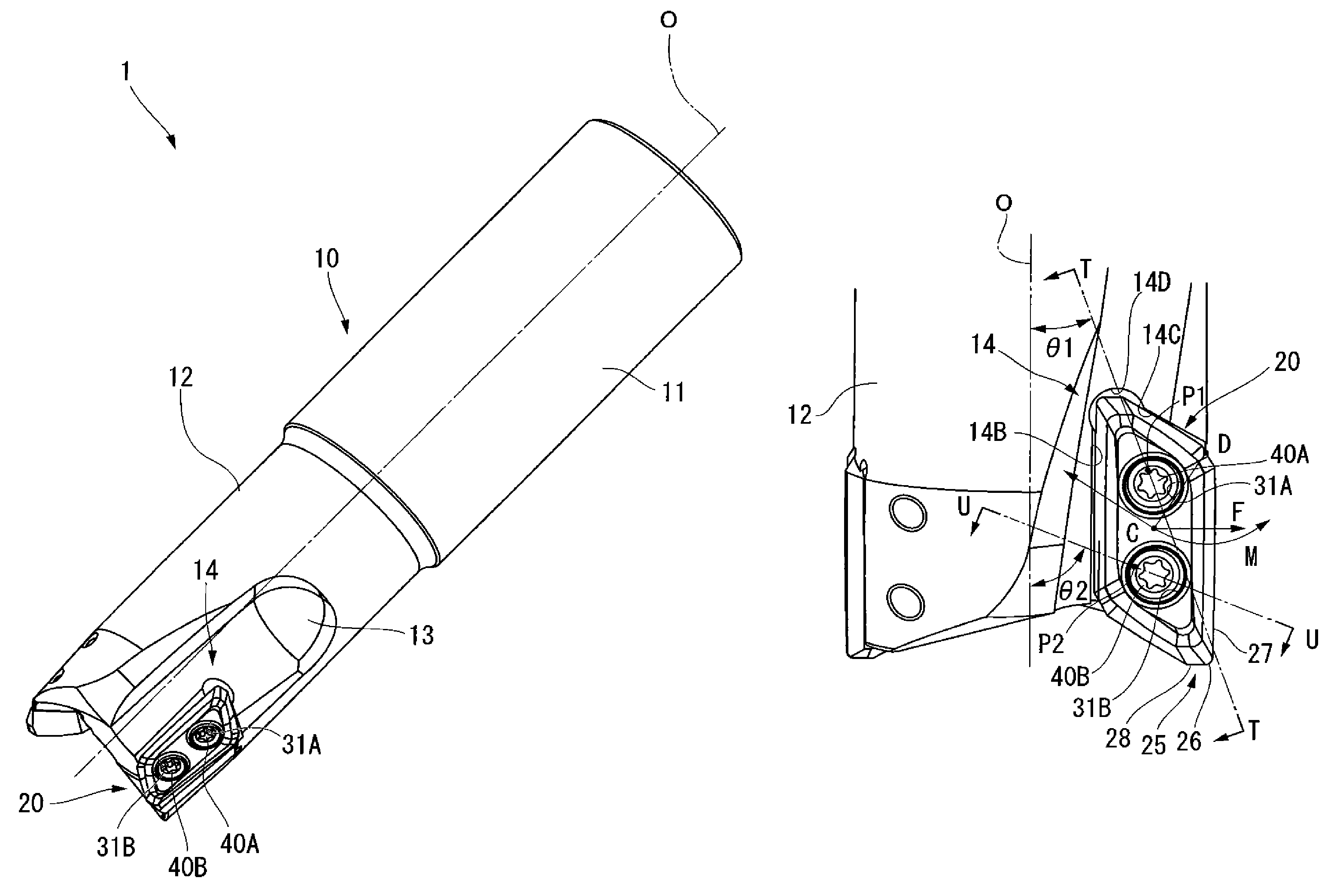
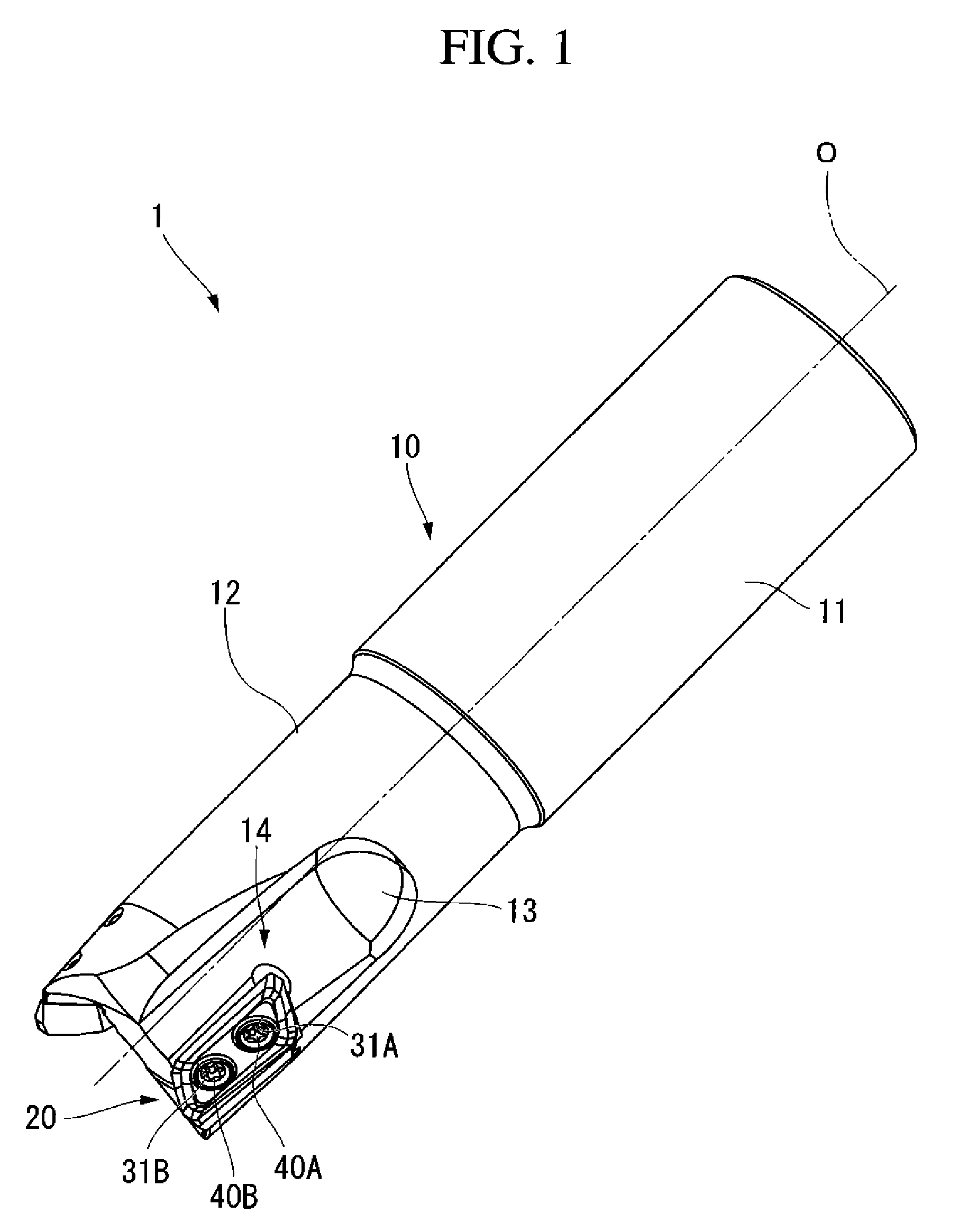
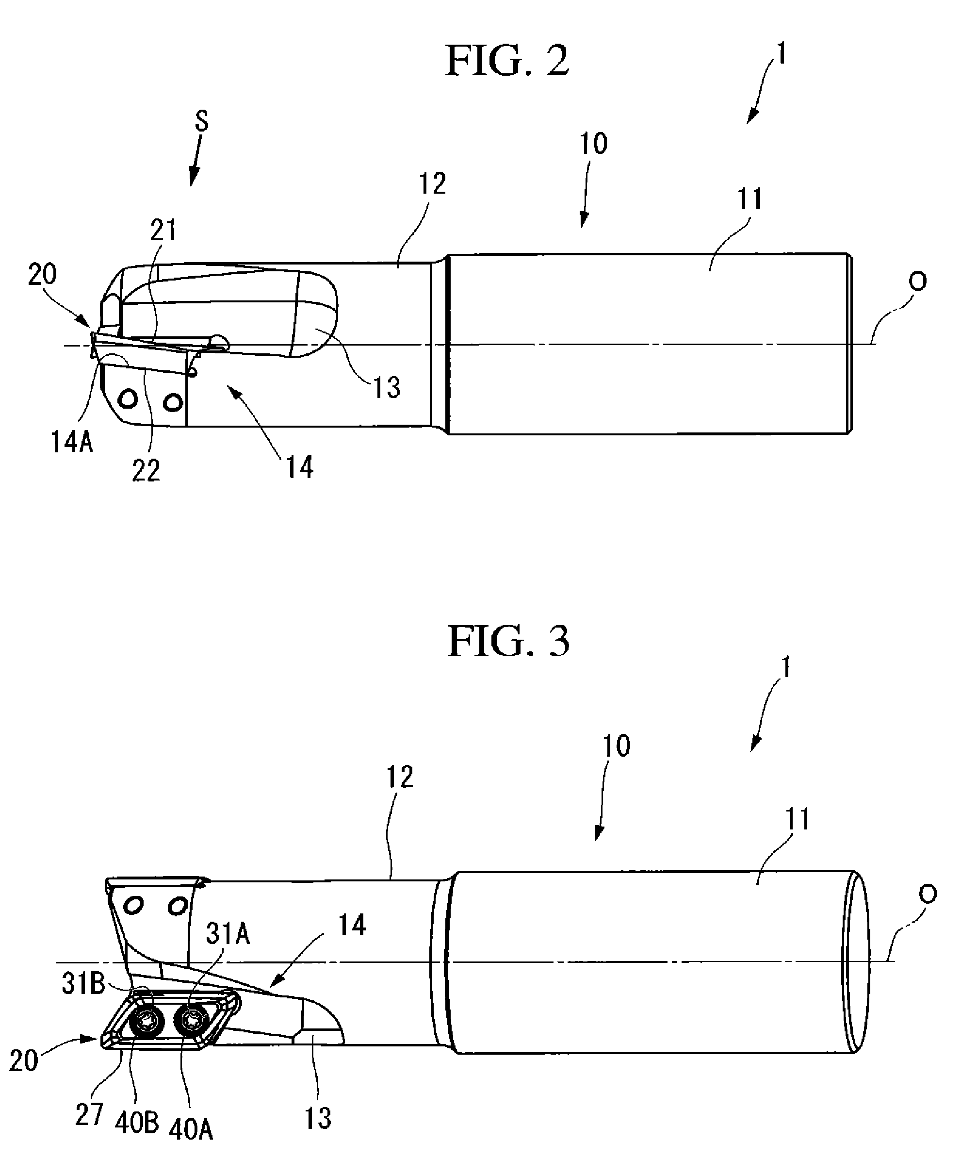
[0043]An embodiment of the present invention is explained with reference to FIG. 1 through FIG. 12. An insert type cutting instrument of the embodiment of the present invention is shown in FIG. 1 through FIG. 8. An instrument main body is shown in FIG. 9, and an insert is shown in FIG. 10 through FIG. 12.

[0044]As shown in FIG. 1 through FIG. 8, an insert type cutting instrument 1 includes an instrument main body 10 formed from steel material and the like, and inserts 20 formed from rigid material such as sintered hard alloy.

[0045]As shown in FIG. 9, the instrument main body 10 is formed like a solid circular cylinder, and a cutting edge portion 12 is provided at a substantially half part of the instrument main body 10 which is close to a base end of the instrument main body 10. A large-diameter portion 11 of which the diameter is larger than that of the cutting edge portion 12 is provided at a substantially half part of the instrument main body which is close to a tip of the instrum...


PUM

PropertyMeasurementUnit
inclination angleaaaaaaaaaa

Abstract

This insert type cutting instrument includes: an insert formed as a flat polygonal plate, and an instrument main body having a first through-hole and a second through-hole are formed in the insert. The insert is mounted on the seat so that the center of the first screw hole is located closer to the axis than the center of the first through-hole and is located closer to a base end of the body than the center of the first through-hole, and the center of the second screw hole is located closer to the axis than the center of a second through-hole and is located closer to the base end of the body than the center of the second through-hole. Each of the first screw hole and the second screw hole is formed to be orthogonal to an attachment surface of the insert seat.

Description

CROSS-REFERENCE TO RELATED APPLICATIONS[0001]Priority is claimed on Japanese Patent Application No. 2006-20949, filed Jan. 30, 2006, and Japanese Patent Application No. 2006-277479, filed Oct. 11, 2006, the content of which is incorporated herein by reference.BACKGROUND OF THE INVENTION[0002]1. Field of the Invention[0003]The present invention relates to an insert type cutting instrument including an instrument main body in which an insert seat is formed and an insert having a cutting edge detachably attached to the insert seat, the insert, and a method for attaching the insert to the instrument main body.[0004]2. Description of the Related Art[0005]As an insert type cutting instrument, the insert type cutting instrument including a circular-cylindrical instrument main body and an insert is well known. In the insert type cutting instrument, the instrument main body has a tip pocket formed on an outer side surface of a head portion of the instrument main body, and an insert seat loca...

Claims


Application Information

Patent Timeline
Patent Type & Authority Patents(United States)
IPC IPC(8): B23C5/20
CPCB23C5/109B23C5/2221B23C2200/203B23C2200/286B23C2200/362B23C2210/045Y10T407/1948B23C2210/168Y10T407/1946Y10T407/23Y10T407/1936Y10T407/1924Y10T407/192B23C2210/0457B23C5/2213B23C2200/287
Inventor SAKAMOTO, TOMOYOSHINARITA, TOURU
Owner MITSUBISHI MATERIALS CORP
Why Eureka
Try Eureka