Radio-frequency coil arrangement

a technology of radio frequency coils and coils, applied in the direction of continuously variable inductance/transformers, instruments, using reradiation, etc., can solve the problems of poor signal-to-noise ratio, complicated or even impossible, etc., and achieve the effect of versatile usage capability

Inactive Publication Date: 2009-10-06
SIEMENS HEALTHCARE GMBH
View PDF18 Cites 4 Cited by
  • Summary
  • Abstract
  • Description
  • Claims
  • Application Information

AI Technical Summary

Benefits of technology

[0007]An object of the present invention is to provide a radio-frequency coil arrangement that allows a versatile usage capability in various application fields.
[0012]For larger radio-frequency coil arrangements it is also conceivable to produce a coil geometry in which coils exhibit different sizes in specific regions. For example, if specific data from body areas should thus be acquired with higher sensitivity, the smallest possible coils (in particular the basic coils) can be used in this region. Other regions in which a lower resolution is required use larger coils, such that readout and reconstruction can be implemented faster and less data produced.
[0021]A number of embodiments are also possible for the concrete embodiment of the switching arrangement. The switching arrangement can thus fashioned as electrostatic relays and / or semiconductor switches and / or galvanic switches. An electrostatic relay in which, for example, various connections of conductor traces can be effected simultaneously by means of a single device, has the advantage that the relay as a single switching means is possibly already sufficient. Such a relay with various positions associated with different coil geometries could then be provided at each node point. Connections of specific conductor trace segments of the node can alternatively be established or interrupted by semiconductor switches or galvanic switches, the switches then being respectively associated with a specific connection section. Semiconductor switches (in particular CMOS switches) are preferable, since these exhibit only a small capacitance.
[0022]If individual switches are used as the switching arrangement, six switches can be appropriately provided at each switchable node point. By means of six such switches, it is possible to establish every possible connection of the four conductor trace segments arriving at the node point, such that in this embodiment a greatest flexibility and design freedom exist with regard to the possible coil geometries.
[0025]Two embodiments are available for transfer of the control signals to the switching arrangement. The control device can include conductors for transfer of the control signals for activation of the switching arrangement or switching arrangements. A separate line can be directed to each of the switching arrangements; for example, in the case of a bus system it is also possible for that the individual switching arrangements to be sequentially connected with one another. The control device can advantageously be fashioned for return conduction of the control signals via the conductor traces such that extra conductor sections are avoided.
[0028]Alternatively or additionally, the switching arrangements can be individually controllable, meaning that the concrete switch setting can be selected independently for each switching arrangement. A large design freedom is thereby achieved.

Problems solved by technology

Although a high measurement field with high penetration depth can be achieved with large coils, these exhibit a poor signal-to-noise ratio due to their large area.
An exchange of the radio-frequency coil arrangement is then required between these applications, which is very complicated or even impossible (in particular given structurally integrated radio-frequency coil arrangements).

Method used


Image

  • Radio-frequency coil arrangement
  • Radio-frequency coil arrangement
  • Radio-frequency coil arrangement

Examples


Embodiment Construction

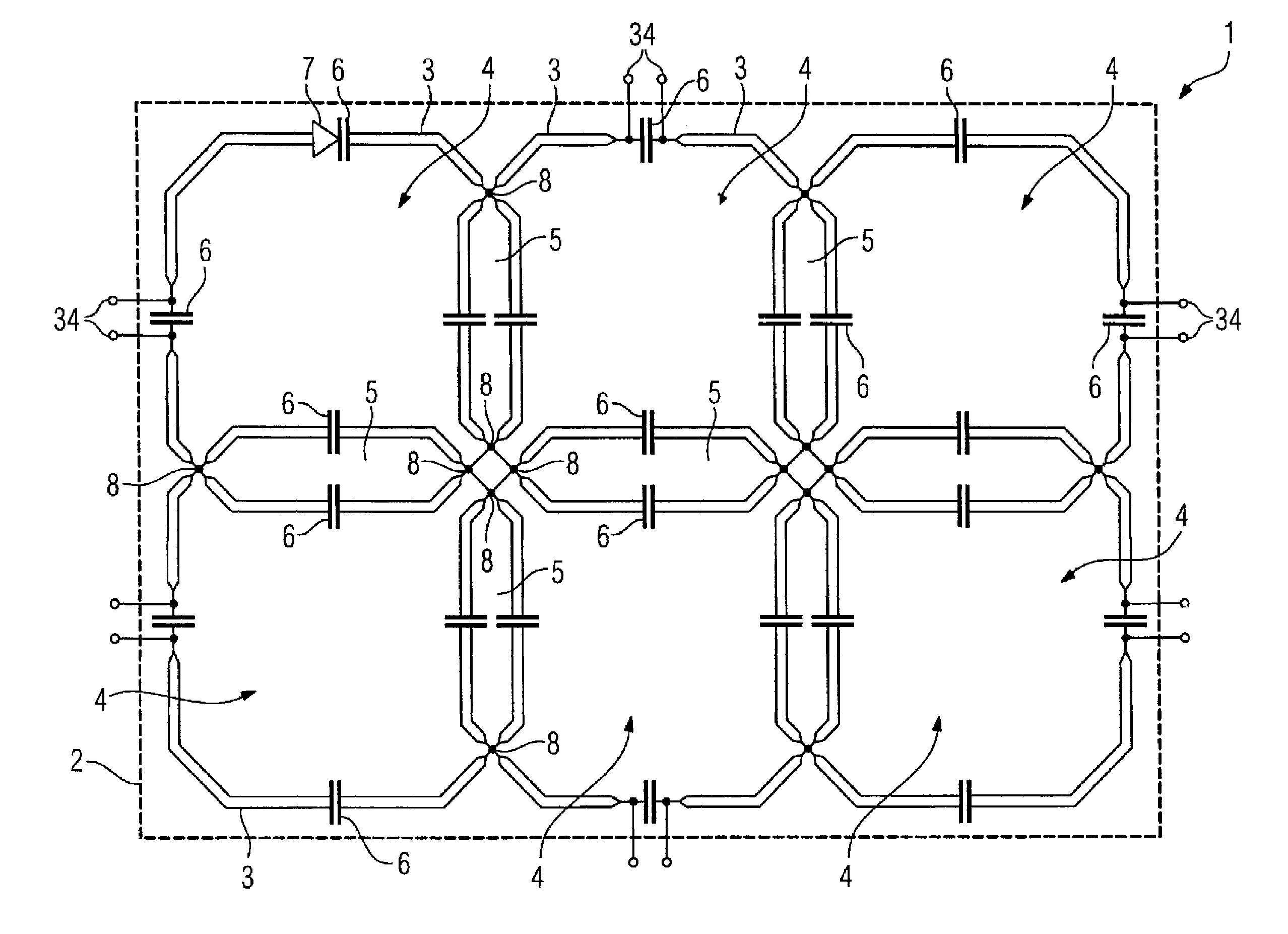
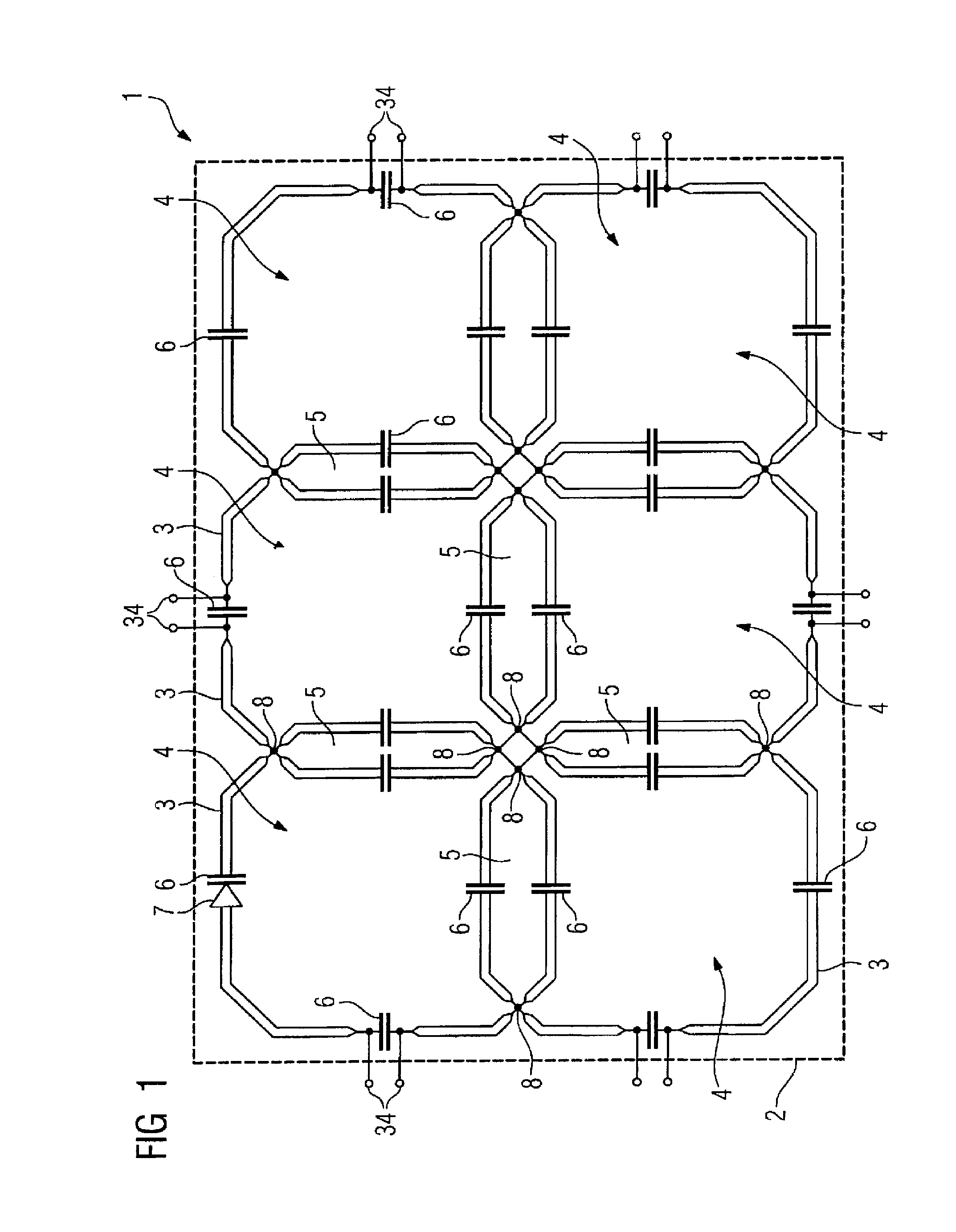
[0042]FIG. 1 shows an inventive radio-frequency coil arrangement 1 according to a first embodiment. The coil arrangement 1 has a circuit board 2 on which are arranged conductor traces 3 that form the basic coils. In this case six essentially rectangular basic coils 4 are provided, but the coil matrix can be arbitrarily enlarged. The basic coils 4 overlap in overlap regions 5 that contribute to the decoupling of the individual basic coils 4 (geometric decoupling).

[0043]Additionally, capacitors 6 that are required for the adjustment of the correct resonance behavior with regard to the inductance of the basic coils 4, and can possibly also contribute to the decoupling, are interconnected in the conductor traces 3. At least some of the capacitors 6 can be designed at as capacitance diodes or varactor diodes 7 in which the capacitance can be set by means of a direct voltage thereto. All capacitors 6 can also be fashioned as capacitance diodes 7. Given different coil geometries the resona...


PUM


Abstract

A radio-frequency coil arrangement has a number of conductor traces forming basic coils and with capacitors interconnected in the conductor traces. Conductor traces of various basic coils intersect at node points. At least one switching arrangement for selective, reversible connection of the conductor traces to form different coil geometries is provided at least some of the node points.

Description

BACKGROUND OF THE INVENTION[0001]1. Field of the Invention[0002]The present invention concerns a radio-frequency coil arrangement of the type having a number of conductor tracks or traces (paths) forming basic coils with capacitors interlaced within said conductor traces, with conductor traces of various basic coils intersecting at node points.[0003]2. Description of the Prior Art[0004]Radio-frequency coil arrangements of the above type are used in magnetic resonance apparatuses, wherein they fulfill a dual function. They serve for the emission (transmission) of radio-frequency fields for excitation of the nuclear spins in a region to be examined; and they also serve for the reception of the measurement signals. A number of single or basic coils that frequently overlap to form overlap regions are embodied in a radio-frequency coil arrangement. These overlap regions can be designed such that the basic coils are decoupled from one another, meaning that they do not mutually influence o...

Claims


Application Information

Patent Timeline
Patent Type & Authority Patents(United States)
IPC IPC(8): G01V3/00
CPCG01R33/3664G01R33/3415G01R33/34084G01R33/34007
Inventor FISCHER, HUBERTUSHEID, OLIVERHERGT, MARTIN
Owner SIEMENS HEALTHCARE GMBH
Why Eureka
Try Eureka