Variable position dampers for controlling air flow to multiple modules in a common chassis

a technology of dampers and chassis, applied in the direction of electrical apparatus casings/cabinets/drawers, cooling/ventilation/heating modifications, support structure mounting, etc., can solve the problem of excessive cooling air flow to the modules

Inactive Publication Date: 2009-10-06
LENOVO GLOBAL TECH INT LTD
View PDF14 Cites 33 Cited by
  • Summary
  • Abstract
  • Description
  • Claims
  • Application Information

AI Technical Summary

Problems solved by technology

As a result, some modules receive an excessive flow rate of cooling air.

Method used


Image

  • Variable position dampers for controlling air flow to multiple modules in a common chassis
  • Variable position dampers for controlling air flow to multiple modules in a common chassis
  • Variable position dampers for controlling air flow to multiple modules in a common chassis

Examples


Embodiment Construction

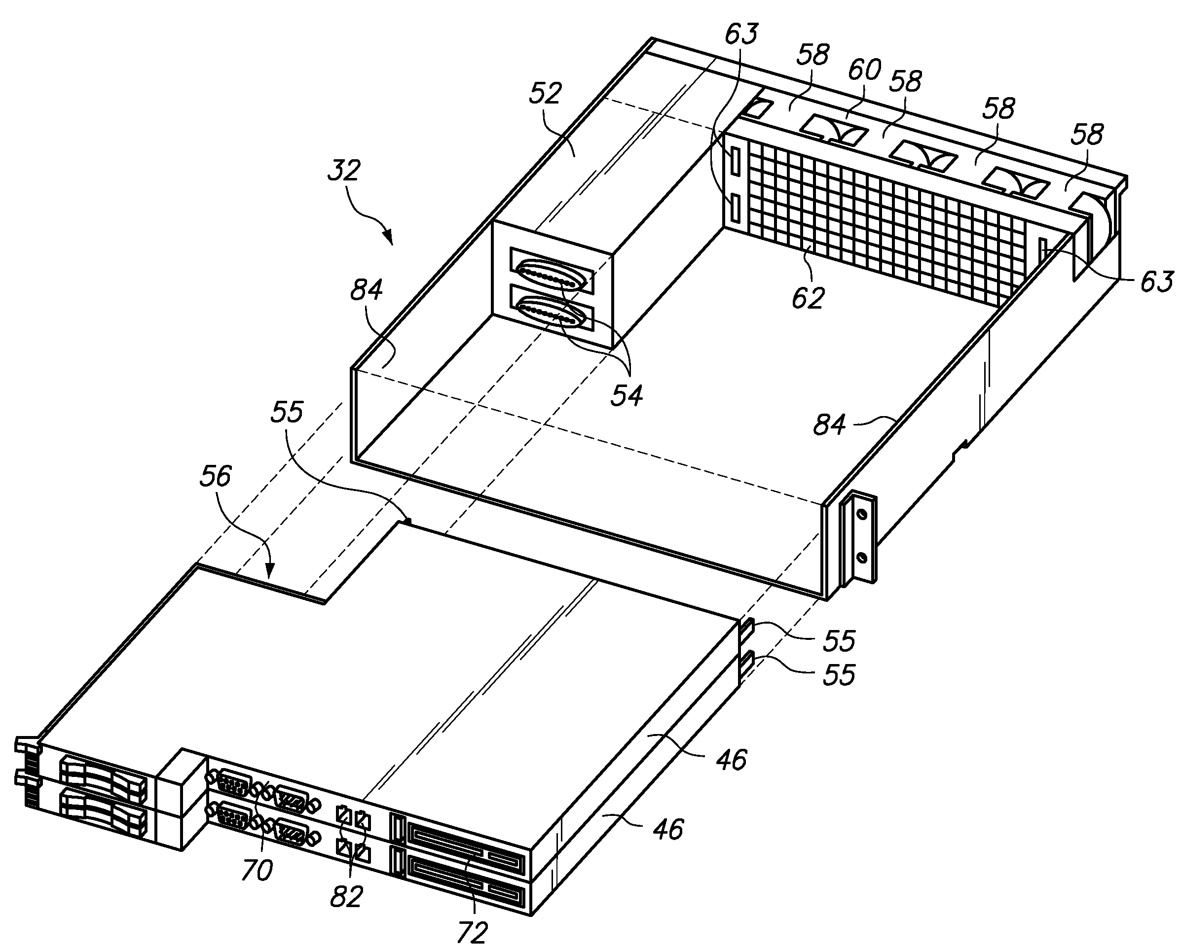
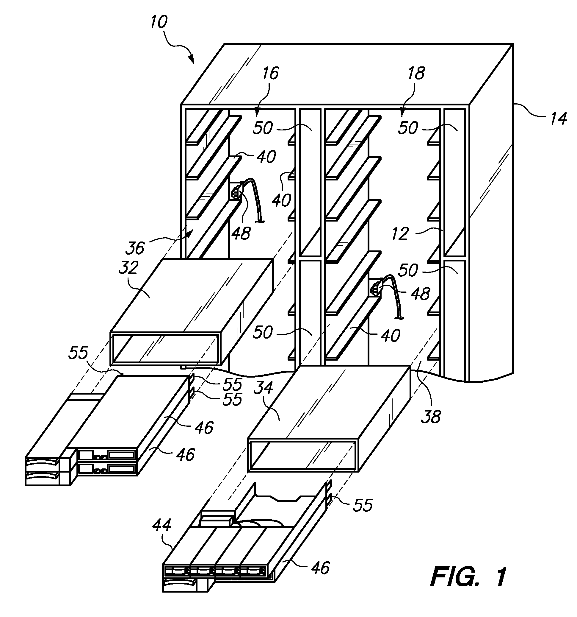
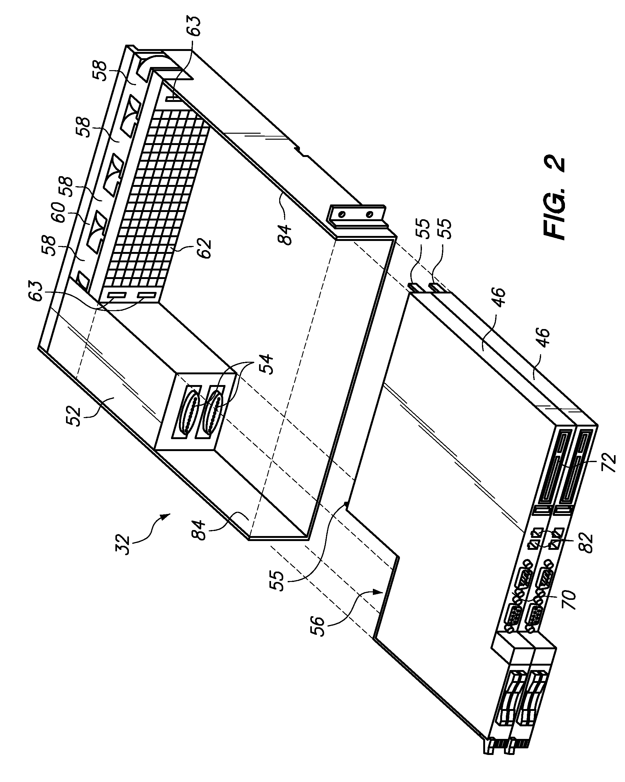
[0023]One embodiment of the invention provides an apparatus comprising a chassis having a proximal end that provides access to a plurality of module bays. One or more modules are each received in one of the module bays, wherein each module has at least one damper actuator distally extending from a distal end of the module. A fan assembly including a plurality of fans is secured in a distal end of the chassis. Between the module bays and the fan assembly is a plurality of air flow dampers, wherein each air flow damper is aligned with one module bay to control air flow through the aligned module bay. Each damper closes in the absence of contact with one of the damper actuators and opens in response to contact with at least one of the damper actuators. When a damper is contacted by a damper actuator as a result of one of the modules being received in one of the module bays, then the damper opens to a variable extent determined by the profile of the damper actuator that is contacting th...


PUM


Abstract

An apparatus comprising a chassis providing a plurality of module bays, one or more modules received in the module bays, wherein each module has at least one damper actuator extending from a distal end of the module. A fan assembly and a plurality of air flow dampers are secured in a distal end of the chassis, wherein each damper is aligned with one module bay to control air flow through the aligned module bay. Each damper is biased to close in the absence of contact with a damper actuator and opens in response to contact with a damper actuator. Each damper opens to a variable extent determined by the profile of the contacting damper actuator. The damper actuator of a particular module has a profile corresponding to the thermal load of that module, such that installing a module into the chassis automatically opens the aligned damper to the desired extent.

Description

BACKGROUND OF THE INVENTION[0001]1. Field of the Invention[0002]The present invention relates to air flow through computer chassis that contain multiple modules.[0003]2. Description of the Related Art[0004]In flexible computer systems, system nodes or modules, such as blade servers, are frequently installed and removed from a chassis. When a module is removed from the chassis, an air flow short circuit is created and the air flow of adjacent modules is reduced. Frequently, the module being removed must be replaced with a substitute module or plate to prevent the redirection of airflow through the vacant bay.[0005]In order to provide an adequate flow rate of cooling air through each individual module, one known system provides each module with its own fan assembly. A controller may then control the speed of the fan assembly in order to control the temperature of components within the module.[0006]Another known system provides a common fan assembly for a plurality of modules, such as ...

Claims


Application Information

Patent Timeline
Patent Type & Authority Patents(United States)
IPC IPC(8): H05K7/20
CPCH05K7/20727
Inventor DITTUS, KARL KLAUSMILLER, MICHAEL SVENSCOTT, III, WHITCOMB RANDOLPHWALKER, JOEL EDWIN
Owner LENOVO GLOBAL TECH INT LTD
Why Eureka
Try Eureka