Electric power converter

a technology converters, applied in the direction of power conversion systems, ac-ac conversion, dc-dc conversion, etc., can solve the problems of troublesome function change work, troublesome combining work, and increase the volume of inventories, so as to facilitate the combining of work and reduce the inventory of electric power converters. , the effect of easy change of function

Active Publication Date: 2009-10-06
MITSUBISHI ELECTRIC CORP
View PDF12 Cites 111 Cited by
  • Summary
  • Abstract
  • Description
  • Claims
  • Application Information

AI Technical Summary

Benefits of technology

[0017]According to the present invention, when the main circuit unit and the control unit that have been stored in a state of being separated from each other and are combined together for shipment, and when the main circuit unit and the control unit that have been separated from each other after having been combined together and are again combined together, there is no need to store characteristics of the main circuit unit, calibration values, a production history, an operation history, and specifications in the control unit, and hence the main circuit unit and the control unit can be easily combined together. Additionally, when a change in function is made according to the change from the control unit to another, there is no need to temporarily upload characteristics of the main circuit unit, calibration values, a production history, an operation history, and specifications to another storage device and no need to download these data to the newly provided control unit, and hence a change in function can be easily made. Additionally, one of various control units differing in the control manner can be detachably attached to a single main circuit unit, and hence the inventory of the electric power converters can be greatly reduced.

Problems solved by technology

Therefore, the combining work is troublesome.
Therefore, the function changing work is troublesome.
This has caused an increase in the volume of inventories.

Method used


Image

  • Electric power converter
  • Electric power converter
  • Electric power converter

Examples


first embodiment

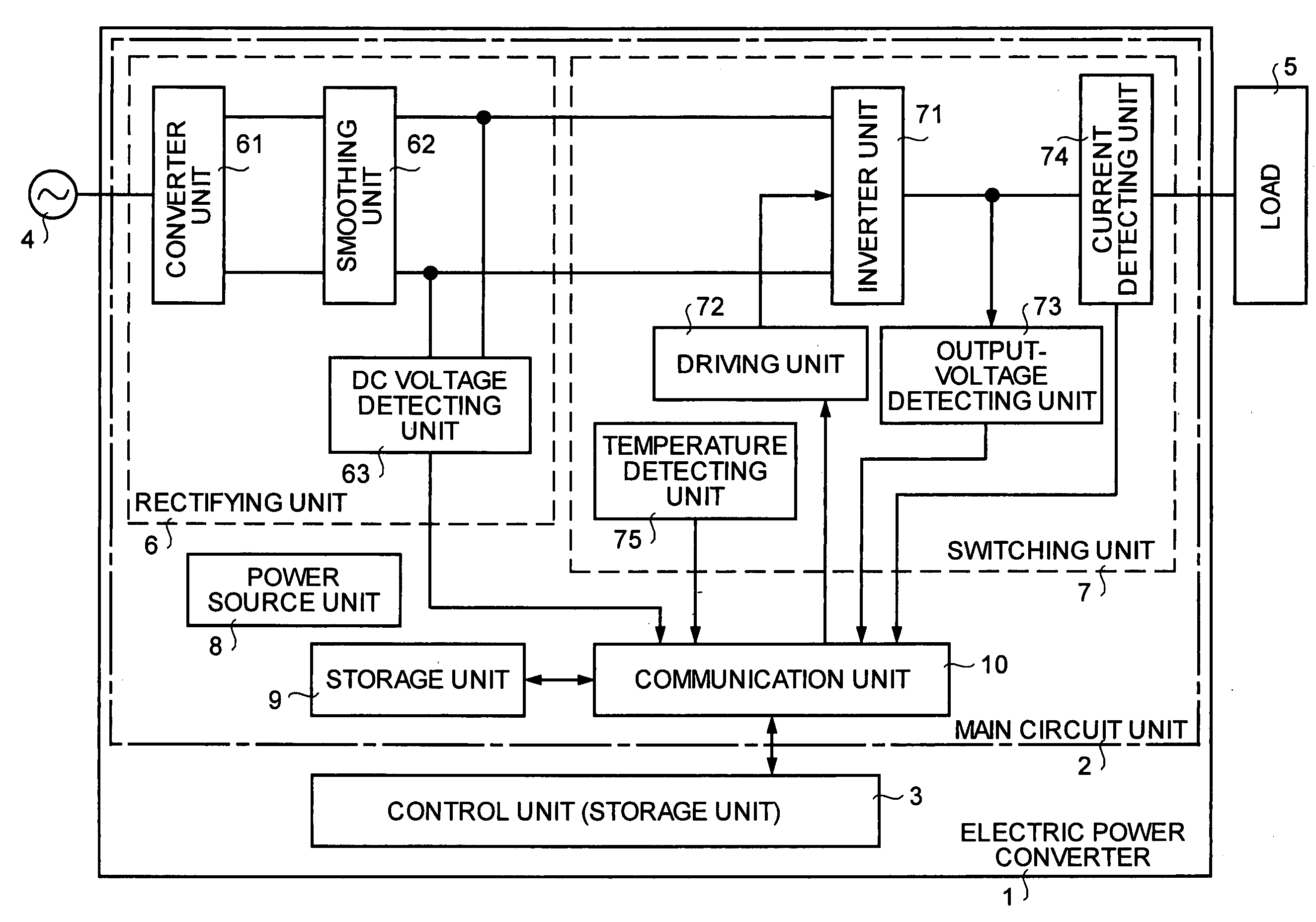
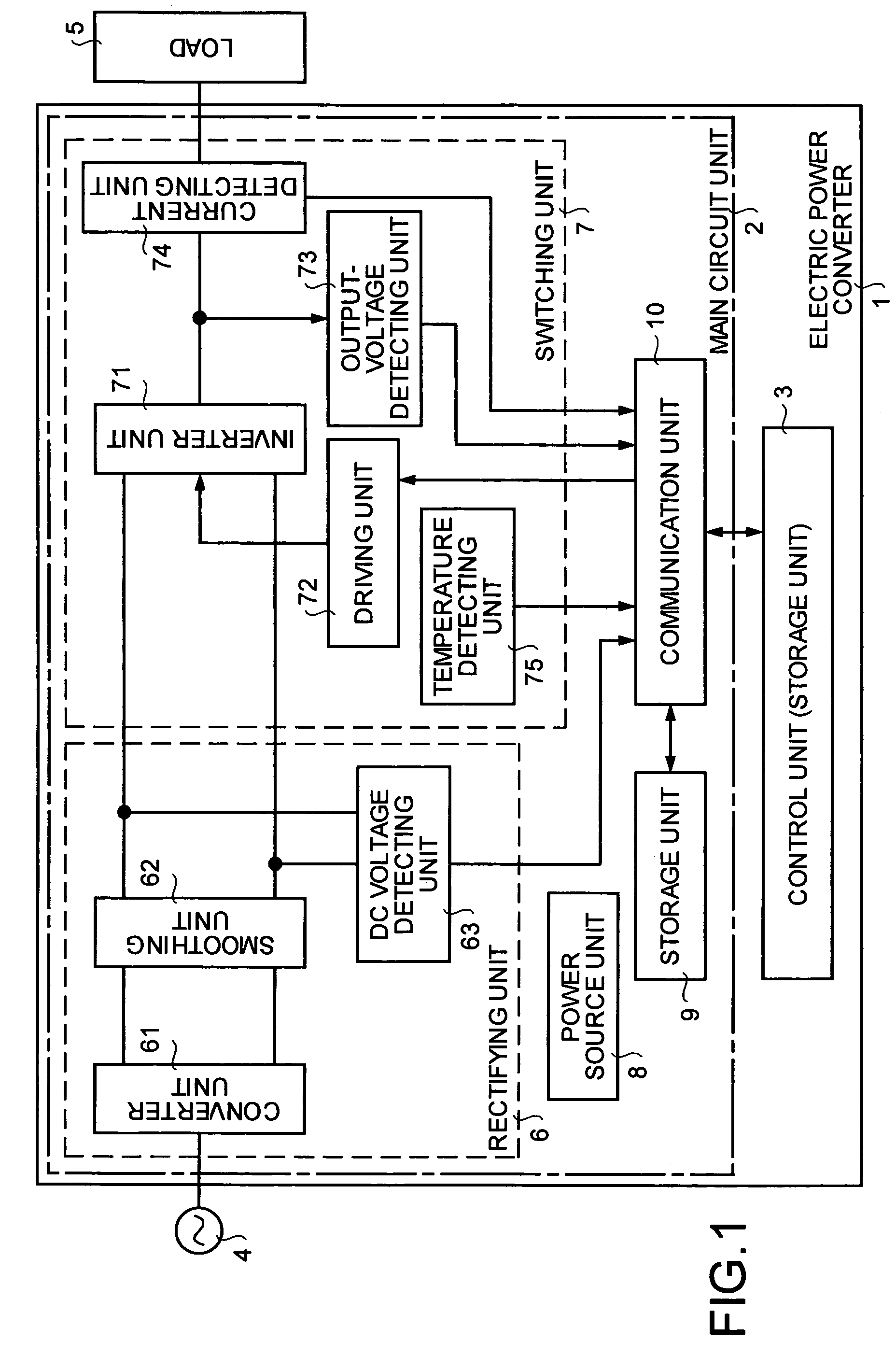
[0024]FIG. 1 is a block diagram of a structure of the electric power converter according to a first embodiment of the present invention. The electric power converter 1 shown in FIG. 1 is made up of a main circuit unit 2 and a control unit 3. The electric power converter 1 generates an AC voltage, which is arbitrary in frequency and voltage, from a commercial AC power source 4, and supplies the voltage to a load 5.

[0025]The main circuit unit 2 includes a rectifying unit 6, a switching unit 7, a power source unit 8, a storage unit 9, and a communication unit 10. The main circuit unit 2 and the control unit 3 are housed in mutually independent cases, respectively, and transmit necessary information to each other through the communication unit 10.

[0026]The rectifying unit 6 includes a converter unit 61 that converts the AC voltage of the commercial AC power source 4 into a DC voltage, a smoothing unit 62 that smoothes the DC voltage converted by the converter unit 61, and a DC voltage d...

second embodiment

[0045]FIG. 4 is a block diagram of a structure of an electric power converter according to a second embodiment of the present invention. In FIG. 4, the same reference numeral as in FIG. 1 (first embodiment) is given to the same or equivalent component. Herein, a description is provided centering about a part relative to the second embodiment.

[0046]As shown in FIG. 4, in the electric power converter 51 according to the second embodiment, the communication unit 10 is omitted in the structure shown in FIG. 1 (first embodiment), and a signal of each unit of the main circuit unit 2 is directly connected to the control unit 3 by one-to-one correspondence. The same operation and effect as in the first embodiment can be obtained by the structure.

third embodiment

[0047]FIG. 5 is a block diagram of a structure of an electric power converter according to a third embodiment of the present invention. In FIG. 5, the same reference numeral as in FIG. 1 (first embodiment) is given to the same or equivalent component. Parts that relate to the third embodiment have only been explained below.

[0048]As shown in FIG. 5, in the third embodiment, a DC power source 55 is provided in parallel with the converter unit 61 at an input terminal of the smoothing unit 62 in the electric power converter 1 shown in FIG. 1 (first embodiment). Although the DC power source 55 is a backup power source, a power source that can supply DC power can be likewise connected. As a result, in the electric power converter designed to be uninterruptible, the same operation and effect as in the first embodiment can be obtained.

[0049]Although an example applied to the first embodiment is shown in the third embodiment, it is obvious that the example is also applicable to the electric ...


PUM


Abstract

In an electric power converter, a main circuit unit and a control unit are detachably attached to each other, and another control unit differing in a control manner can be newly attached to the single main circuit unit.Moreover, the main circuit unit includes a storage unit that stores at least characteristics concerning the main circuit unit, calibration values with respect to the various detectors, a production history, an operation history, and specifications.

Description

TECHNICAL FIELD[0001]The present invention relates to an electric power converter.BACKGROUND ART[0002]Generally, an electric power converter that, drives an alternate current (AC) load at an arbitrary frequency includes a main circuit unit and a control unit. The main circuit unit includes a switching unit that performs switching from a direct current (DC) voltage (which includes a DC voltage generated from an AC voltage) to an AC voltage having an arbitrary frequency and that outputs the AC voltage. The control unit controls a switching element that is a component of the switching unit based on information concerning the operation of a preset load and information transmitted from various detectors included in the main circuit unit so that the switching element reaches a desired ON / OFF operational state.[0003]Electric power converters that perform open-loop control with ease or products that perform closed-loop control with high accuracy so that a user can use the product in a contr...

Claims


Application Information

Patent Timeline
Patent Type & Authority Patents(United States)
IPC IPC(8): H02M5/40H02J3/00H02M5/45H02M5/458H02M7/5387
CPCH02M7/53873H02M5/458H02M7/48
Inventor TOMONAGA, SHINZO
Owner MITSUBISHI ELECTRIC CORP
Why Eureka
Try Eureka