Method and apparatus for monitoring end-to-end performance in a network

a technology of network end-to-end performance and monitoring method, which is applied in the direction of data switching network, frequency-division multiplex, instruments, etc., can solve the problem that network providers who only monitor core network performance often do not provide the same view of end-to-end performance of services experienced by customers, so as to achieve the effect of fast identification and resolution of network problems

Inactive Publication Date: 2009-10-06
AMERICAN TELEPHONE & TELEGRAPH CO
View PDF14 Cites 56 Cited by
  • Summary
  • Abstract
  • Description
  • Claims
  • Application Information

AI Technical Summary

Benefits of technology

[0004]In one embodiment, the present invention enables edge components, such as Border Elements, of the service provider's network to capture performance data on all endpoints connected to them including registered devices (e.g., CPE gateways, IP phones, and terminal adaptors) and access links. Broadly defined, the Border Element is a network element that represents the edge of a VoIP network and serves as a gateway between a customer's network, a VoIP network, and a Public Switched Telephone Network (PSTN). The present invention enables the performance data to be sent to a centralized repository that consolidates information across the entire network, analyzes it, and segments it with respect to location of events that cause defects in calls. The performance data can then be graphically mapped into predefined network segmentations to enable faster identification and resolution of network problems. Furthermore, the tool would enable the refinement of a generic and ambiguous defect code indicating “resource unavailable” to distinguish between Customer Premise Equipment (CPE) errors, access link errors, customer gateway errors, or voice mail errors.

Problems solved by technology

Current error detection tools typically monitor the service provider's core portion of the network, ignore access portions of the network and have ambiguous categorization of access network defects.
From a customer point of view, network providers who only monitor core network performance often does not provide the same view of the end-to-end performance of the services experienced by the customer.

Method used


Image

  • Method and apparatus for monitoring end-to-end performance in a network
  • Method and apparatus for monitoring end-to-end performance in a network
  • Method and apparatus for monitoring end-to-end performance in a network

Examples


Embodiment Construction

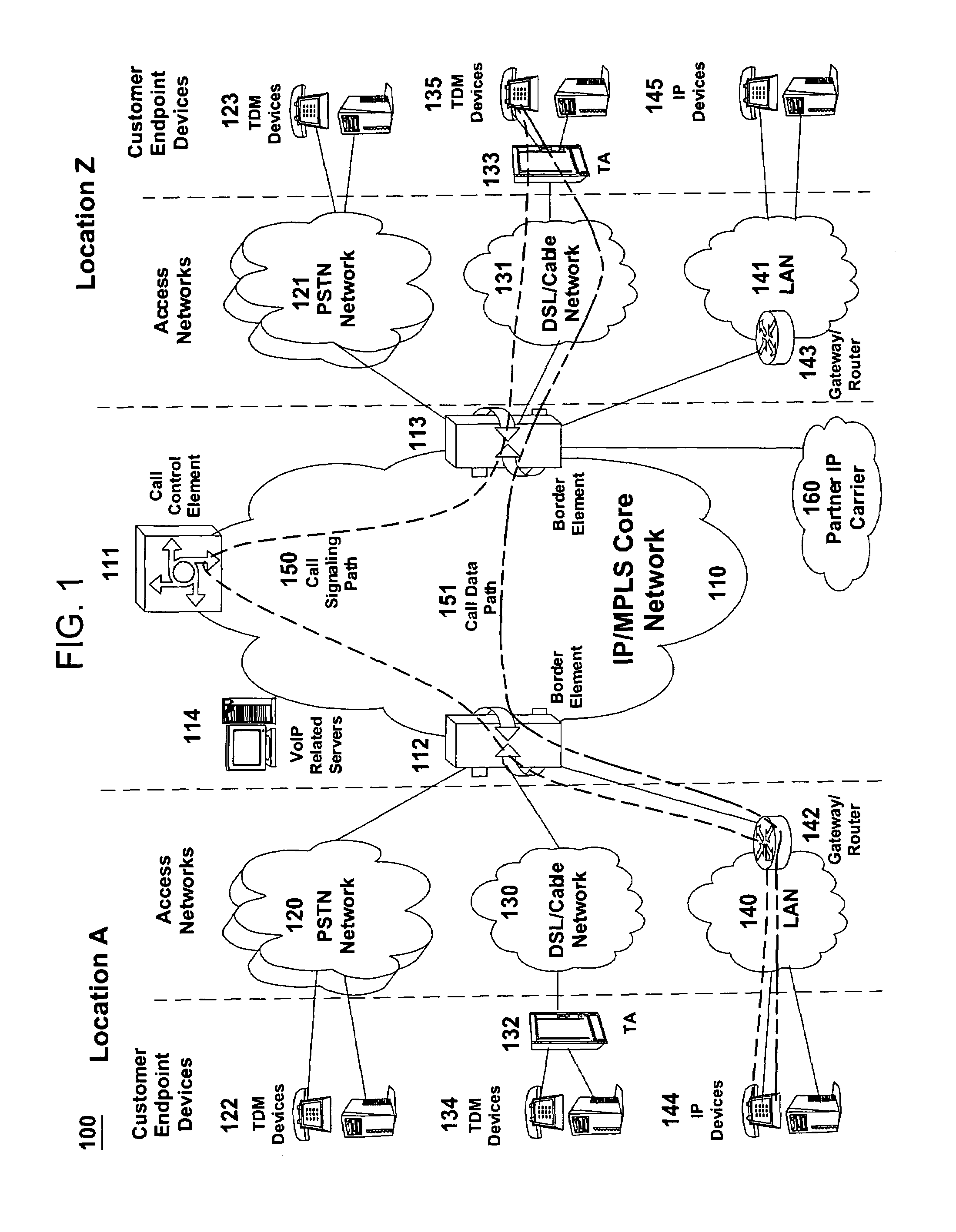
[0012]To better understand the present invention, FIG. 1 illustrates an example network, e.g., a packet-switched network such as a VoIP network related to the present invention. The VoIP network may comprise various types of customer endpoint devices connected via various types of access networks to a carrier (a service provider) VoIP core infrastructure over an Internet Protocol / Multi-Protocol Label Switching (IP / MPLS) based core backbone network. Broadly defined, a VoIP network is a network that is capable of carrying voice signals as packetized data over an IP network. An IP network is broadly defined as a network that uses Internet Protocol to exchange data packets.

[0013]The customer endpoint devices can be either Time Division Multiplexing (TDM) based or IP based. TDM based customer endpoint devices 122, 123, 134, and 135 typically comprise of TDM phones or Private Branch Exchange (PBX). IP based customer endpoint devices 144 and 145 typically comprise IP phones or PBX. The Ter...


PUM


Abstract

The present invention enables edge components, such as Border Elements, of the service provider's network to capture performance data on all endpoints connected to them including registered devices (e.g., CPE gateways, IP phones, and terminal adaptors) and access links. The present invention enables the performance data to be sent to a centralized repository that consolidates information across the entire network, analyzes it, and segments it with respect to location of events that cause defects in calls. The performance data can then be graphically mapped into predefined network segmentations to enable faster identification and resolution of network problems.

Description

[0001]The present invention relates generally to communication networks and, more particularly, to a method and apparatus for monitoring end-to-end performance in a packet-switched network, e.g., a Voice over Internet Protocol (VoIP) network.BACKGROUND OF THE INVENTION[0002]VoIP network operators who are trying to achieve a high level of service availability need to monitor their network from an end-to-end view. Current error detection tools typically monitor the service provider's core portion of the network, ignore access portions of the network and have ambiguous categorization of access network defects. Very often, performance data showing a healthy core network does not necessarily mean a healthy access network. From a customer point of view, network providers who only monitor core network performance often does not provide the same view of the end-to-end performance of the services experienced by the customer.[0003]Therefore, a need exists for a method and apparatus for monito...

Claims


Application Information

Patent Timeline
Patent Type & Authority Patents(United States)
IPC IPC(8): H04L12/66
CPCG06Q10/0639H04L41/5009H04L41/5087H04L41/22
Inventor CROAK, MARIANESLAMBOLCHI, HOSSEIN
Owner AMERICAN TELEPHONE & TELEGRAPH CO
Why Eureka
Try Eureka