Walk-type lawn mower and catcher frame apparatus

a walk-type, lawn mower technology, applied in mowers, agriculture tools and machines, agriculture, etc., can solve the problems of weight increase of lawn chips l stored in the grass catcher g′, front roller b, and weight loss

Active Publication Date: 2009-10-13
KYOEISHA
View PDF15 Cites 9 Cited by
  • Summary
  • Abstract
  • Description
  • Claims
  • Application Information

AI Technical Summary

Benefits of technology

[0007]Accordingly, it is an object of the present invention to provide a lawn mower of a “machine-body integrated type” having a configuration in which the weight of lawn chips does not affect a front roller of a lawn mowing unit even when the weight is increased with the lawn chips stored in a grass catcher, and being able to mow the lawn at a preset mowing height from the beginning to the end of the mowing operation.
[0010]The catcher supporting unit is connected to the machine body via the connecting rod so as to be capable of rotating about the axis of rotation which extends in the direction of the width of the machine body. Therefore, when the lawn surface is inclined along the direction of travel of the machine body, the catcher supporting unit rotates with respect to the machine body by an angle corresponding to the inclination and hence the catcher roller is constantly in touch with the lawn surface during the travel. In other words, regarding the inclination of the lawn surface along the direction of travel of the machine body, the catcher roller mounted to the front lower end of the catcher supporting unit and the front roller of the lawn mowing unit follow the inclined surface independently and hence the front roller of the lawn mowing unit which determines the mowing height is prevented from lifting, so that the lawn is mowed constantly at a preset mowing height. Since the catcher roller mounted to the front lower end of the catcher supporting unit travels at the forefront of the machine body, it functions as a dewlap roller when mowing a lawn moist with dew, and hence the mowing operation for the lawn moist with dew is smoothly carried out.
[0014]According to the third aspect of the invention, the catcher supporting unit and the catcher roller mounted to the front lower end of the catcher supporting unit are prevented from lowering excessively with respect to the machine body or from inclining excessively in the direction of the width when an operator presses the handle downward to lift the front portion of the machine body for rotating the lawn mower.
[0018]According to the fifth aspect of the invention, with the employment of the connector having a simple structure, the catcher frame is mounted to the first connecting bracket mounted to the back surface of the machine body which faces the operator so as to be rotatable in two different directions independently about the axial centers of the direction of travel of the machine body and of the direction of the width of the machine body.

Problems solved by technology

However, it has such a drawback that the weight of lawn chips L stored in the grass catcher G′ increases in proportion to the amount of mowing operation and the weight is applied to a front roller 4′ of the lawn mowing unit U′ directly and causes the front roller 4′ to weigh down.
Therefore, there arises a problem such that when the weight of the lawn chips L stored in the grass catcher G′ increases in association of the progress of the mowing operation, the amount of weighing down of the front roller 4′ of the lawn mowing unit U′ gradually increases, and hence the mowing height of the lawn is gradually lowered.
However, since the number of components is significantly large, and the entire length of the lawn mower is long, a large force is required when the operator pushes down a handle to lift the lawn mowing unit U″ to change the direction of mowing during the mowing operation or to transfer the lawn mower and, simultaneously, since the lawn mowing unit U″ is brought into a state of being suspended by a chain 93 from the unit frame 91, the operator needs to push the handle down by a large amount correspondingly, which deteriorates the operability.

Method used


Image

  • Walk-type lawn mower and catcher frame apparatus
  • Walk-type lawn mower and catcher frame apparatus
  • Walk-type lawn mower and catcher frame apparatus

Examples


Embodiment Construction

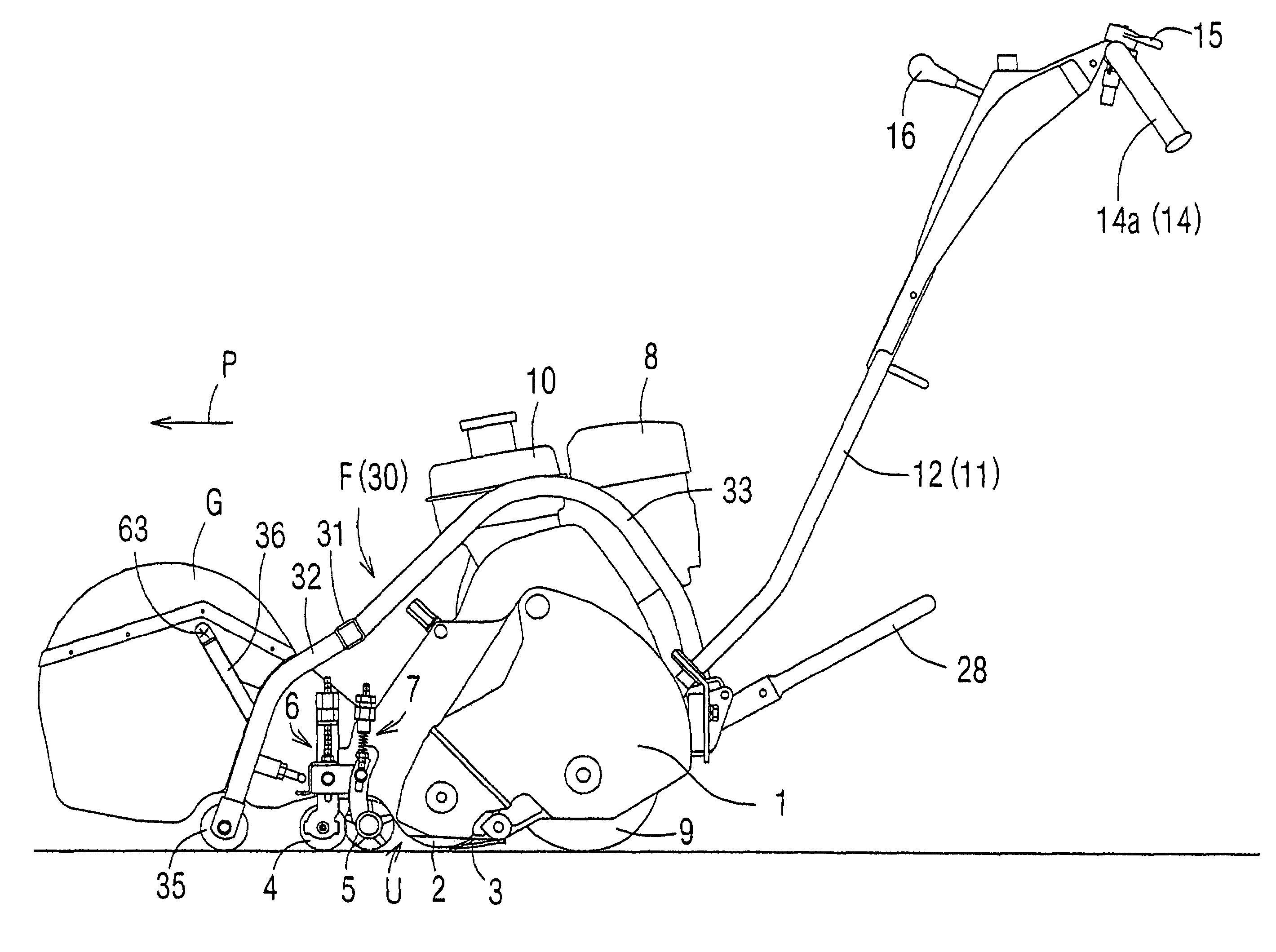
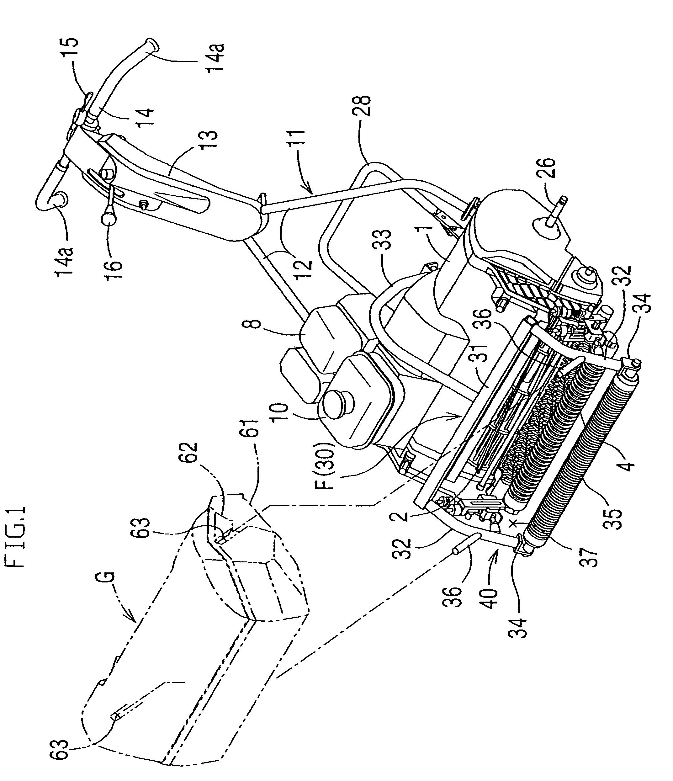
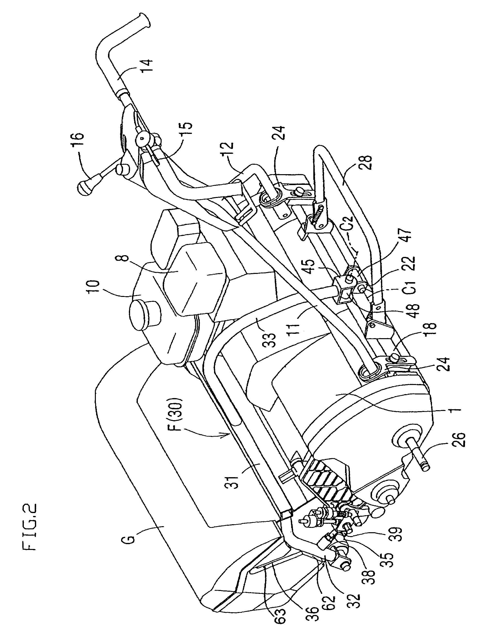
[0033]The present invention will be described further in detail on the basis of a preferred embodiment exemplified here. FIG. 1 and FIG. 2 are perspective views of a walk-type lawn mower (hereinafter, simply referred to as “lawn mower”) according to the present invention when viewed obliquely front and rear, respectively, and FIGS. 3, 4 and 5 are a side view, a plan view and a back view of the same lawn mower respectively. The lawn mower includes a lawn mowing unit U integrally provided to the front portion of a machine body 1. The lawn mowing unit U includes a reel cutter 2 which is driven to rotate about the axial center extending in the direction of the width thereof, a fixed cutter 3 for mowing the lawn in cooperation with the reel cutter 2, a front roller 4 arranged in front of the reel cutter 2 for determining the mowing height of the lawn and a thatching roller 5 arranged between the reel cutter 2 and the front roller 4 for raking dried grass or the like biting in the lawn be...


PUM


Abstract

A catcher frame apparatus is provided including a catcher frame and a catcher roller mounted to the front lower end of a catcher supporting unit of the catcher frame along the direction of the width of a machine body. The catcher frame is connected to the machine body so as to be capable of rotating about an axis of rotation extending along the direction of the width of the machine body, and the catcher supporting unit of the catcher frame is arranged in front of a lawn mowing unit, so that substantially the entire weight of lawn chips stored in a grass catcher supported by the catcher supporting unit is applied to the catcher roller.

Description

BACKGROUND OF THE INVENTION[0001]1. Field of the Invention[0002]The present invention relates to a walk-type lawn mower including a lawn mowing unit mounted integrally thereto in front of a machine body and a grass catcher for storing lawn chips arranged in front of the lawn mowing unit and being configured to be operated as an operator walks behind the machine body, and a catcher frame apparatus.[0003]2. Description of the Related Art[0004]The walk-type lawn mower in the above form is generally classified into two types depending on the mounting structure of the lawn mowing unit to the machine body. One is a type having a lawn mowing unit U′ provided integrally in front of a machine body 1′ and a grass catcher G′ detachably attached to a frame of the lawn mowing unit U′ as shown in FIG. 10, which is referred to as “machine-body integrated type”, hereinafter (see FIG. 4 in Japanese Patent No. 3884055). The other one is a type having a lawn mowing unit U″ mounted in front of a machin...

Claims


Application Information

Patent Timeline
Patent Type & Authority Patents(United States)
IPC IPC(8): A01D43/06A01D43/00
CPCA01D43/063
Inventor HIBI, YOSHIHISAPARRIS, GRAEME SIDNEYHAYASHI, AKIO
Owner KYOEISHA
Why Eureka
Try Eureka