
Reciprocating saw blade with tapered tang stem

a saw blade and tang stem technology, applied in the field of reciprocating saw blades, can solve the problems of inability to significantly increase the overall width of the tang stem, the juncture of the tang body and the tang stem can be subject the tang body and the tang stem can be subjected to relatively high stresses, so as to facilitate effective and efficient engagement of the saw blade and increase strength or resistance to fatigue.

Inactive Publication Date: 2009-10-13
BLACK & DECKER INC
View PDF35 Cites 49 Cited by
  • Summary
  • Abstract
  • Description
  • Claims
  • Application Information

AI Technical Summary

Benefits of technology

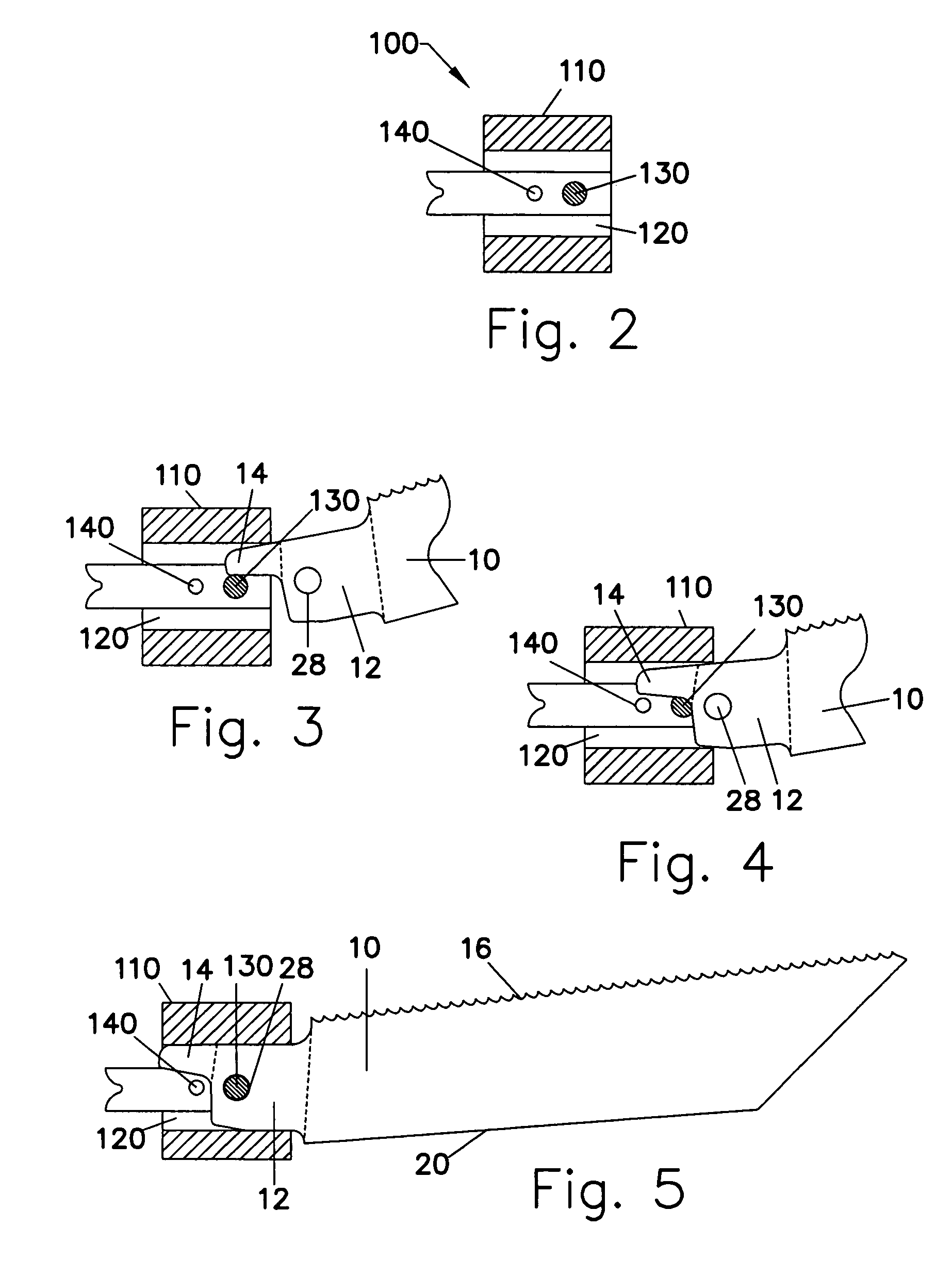
[0012]One advantage of the present invention is that the profile of the tang and tang stem facilitates effective and efficient engagement of the saw blade with any of a variety of different chucks or other clamping devices for reciprocating saws. The improved tang / stem profile of the present invention also advantageously provides for increased strength or resistance to fatigue in comparison to prior art reciprocating saw blades as described above, while nevertheless being usable with a variety of both keyed and keyless chucks.

Problems solved by technology

As a result, reciprocating saw blades typically fail at the juncture of the tang and stem, and / or at a line extending approximately between the points of tangency of the curvilinear portions of the tang formed at the juncture of the tang and blade portion.
However, as described above, chucks typically engage the tang with a drive pin, and along the front edge of both the tang body and tang stem such that the juncture of the tang body and tang stem can be subjected to relatively high stresses.
Thus, although it would be desirable to increase the width of the tang stem, particularly for use in chucks free of internal obstructions, in order to better withstand the tensile and compressive stresses created at the juncture of the tang body and tang stem, the overall width of the tang stem cannot be significantly increased without interfering with internal components associated with certain chucks.
However, the width of the tang in this area cannot be significantly increased without preventing the tang from properly fitting within certain conventional reciprocating saw chucks.

Method used


Image

  • Reciprocating saw blade with tapered tang stem
  • Reciprocating saw blade with tapered tang stem
  • Reciprocating saw blade with tapered tang stem

Examples


Embodiment Construction

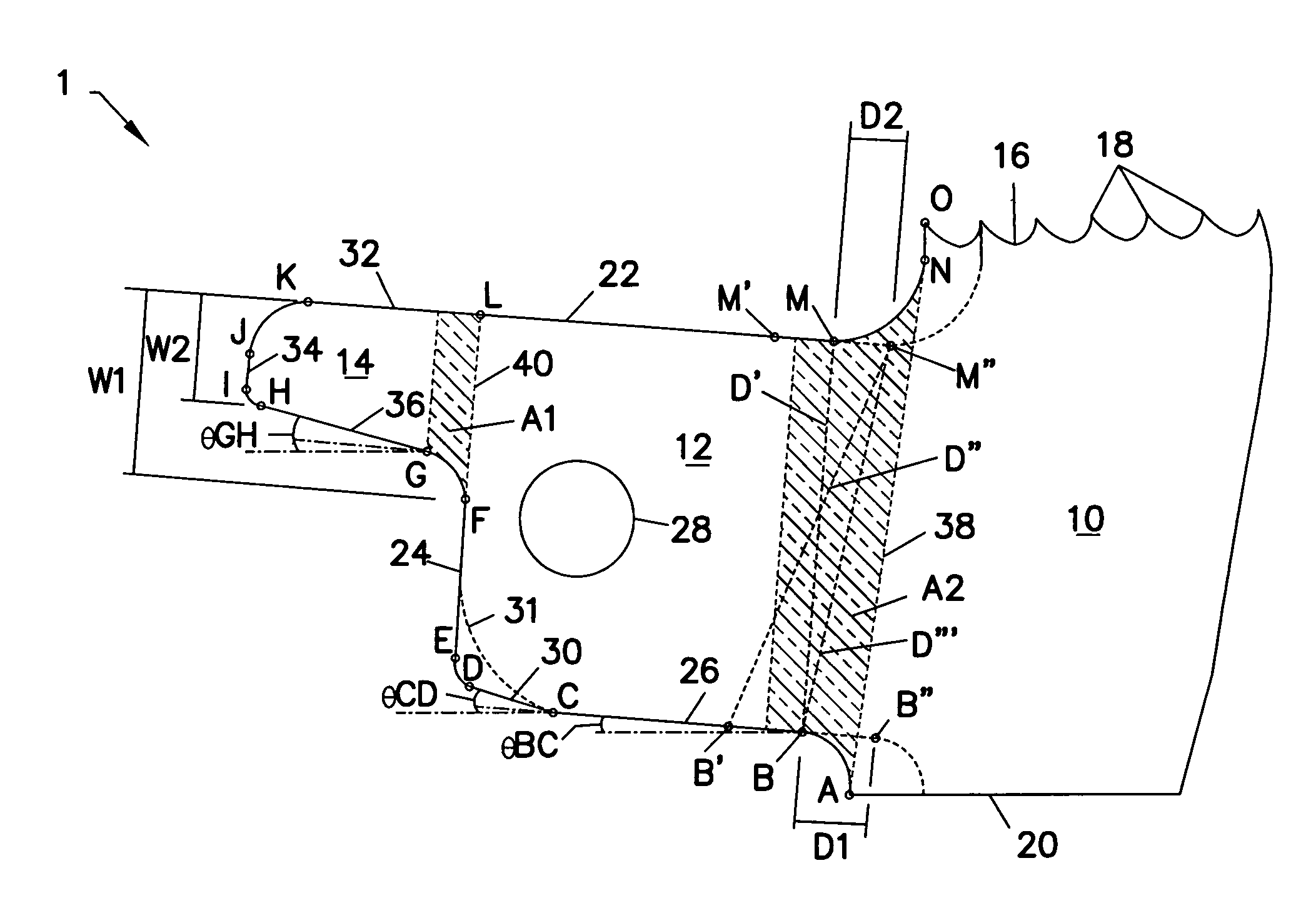
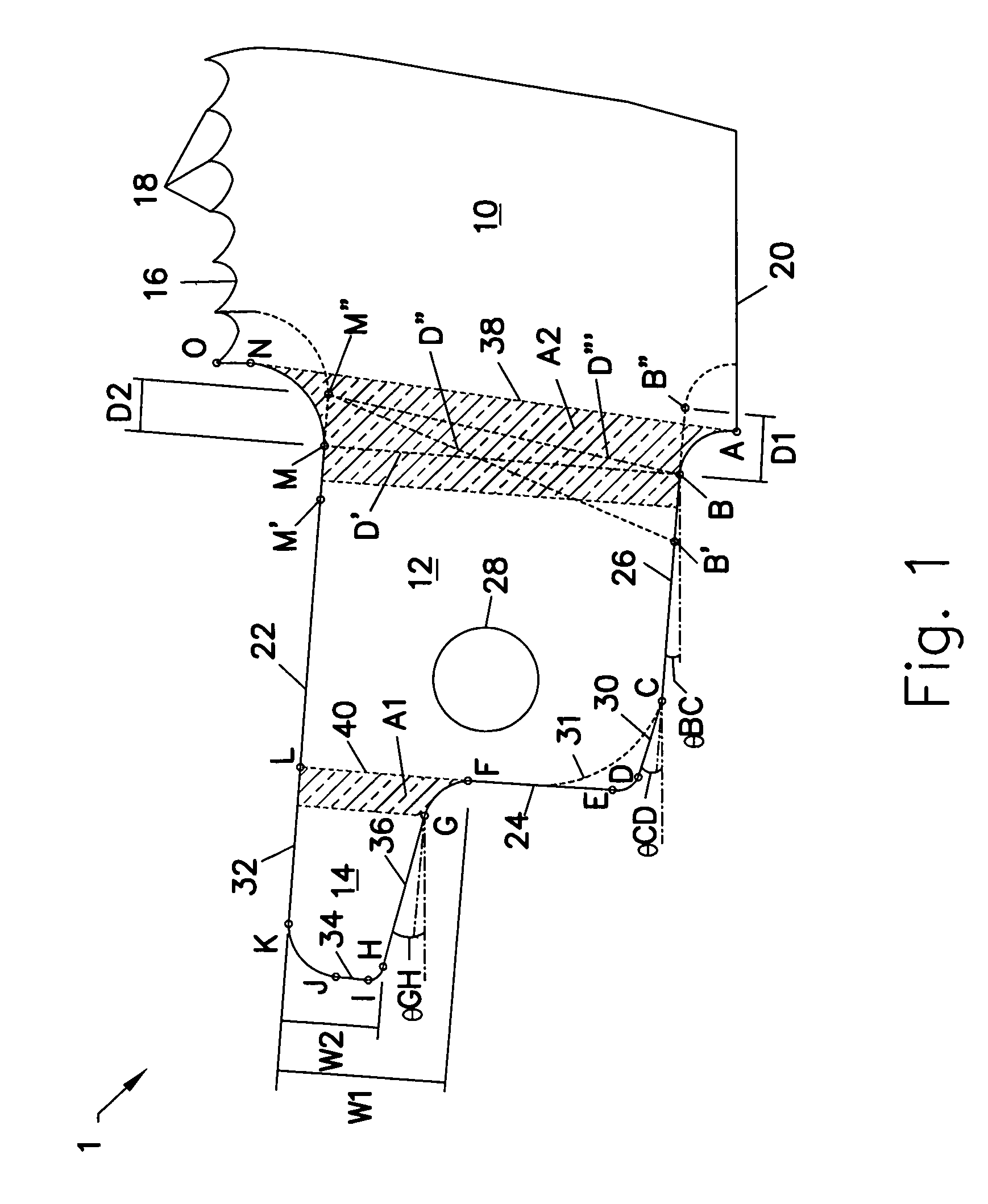
[0030]Referring to the drawings and, in particular, FIG. 1, an enlarged end section of a reciprocating saw blade in accordance with an illustrative embodiment of the present invention is shown and generally represented by the reference numeral 1. As shown, the saw blade 1 has at least a blade portion 10, a tang portion 12, and a stem portion 14. The illustrated blade portion 10, tang portion 12 and stem portion 14 are integrally formed and / or connected. However, as may be recognized by those of ordinary skill in the pertinent art based on the teachings herein, the various portions of the blade may be constructed in any of numerous different ways that are currently known, or later become known. The word “tang” is used herein to mean the portion or projection on or otherwise associated with the blade by which it is attached to a chuck or other device for cutting work pieces with the blade, the words “tang body” or “tang portion” are used herein to mean the main part of the tang that i...


PUM

PropertyMeasurementUnit
angleaaaaaaaaaa
angleaaaaaaaaaa
widthaaaaaaaaaa

Abstract

There is provided a reciprocating saw blade having a tapered tang stem. The tang has a tang portion with at least three outer edges and a stem portion with at least three outer edges. The profiles of the tang portion and particularly the stem portion are such that they facilitate the effective and efficient engagement of the saw blade with any of numerous different keyed or keyless chucks of reciprocating saws. The tang / stem profile also advantageously provides for increased strength for resisting failure and / or fatigue stemming from a cutting force applied to the saw blade during use.

Description

CROSS-REFERENCE TO RELATED APPLICATION[0001]This application claims priority on U.S. Provisional Application Ser. No. 60 / 563,295, filed Apr. 16, 2004, titled “Reciprocating Saw Blade with Tapered Tang Stem”, which is hereby incorporated by reference in its entirety.FIELD OF THE INVENTION[0002]The present invention relates generally to saw blades, and more particularly, to reciprocating saw blades for cutting wood, metal and / or other materials, and that have tangs configured to withstand stresses created at the juncture of a tang body and a tang stem during cutting.BACKGROUND INFORMATION[0003]A typical reciprocating saw blade comprises a blade portion having a cutting edge defined by a plurality of teeth axially spaced relative to each other along one side of the blade, and a non-working edge formed on an opposite side of blade relative to the cutting edge. A tang for releasably connecting the blade to the chuck of a reciprocating saw has a tang body formed on the inner end of the bl...

Claims


Application Information

Patent Timeline
Patent Type & Authority Patents(United States)
IPC IPC(8): B26D1/00B27B19/09B23D49/10B23D51/08B23D61/12
CPCB23D61/123B23D51/08Y10T83/9457Y10T83/9319Y10T83/9348Y10T83/936
Inventor HAMPTON, STEPHEN A.KORB, WILLIAM B.
Owner BLACK & DECKER INC
Learn More