Oil pressure supply circuit for industrial vehicle

a technology for industrial vehicles and oil pressure supply circuits, which is applied in the direction of fluid couplings, servomotors, couplings, etc., can solve the problems of unfavorable effects, and the recovery of the decreased oil pressure supplied to the power steering device takes a long time, so as to ensure the stability of the action

Active Publication Date: 2009-10-13
NISSAN FORKLIFT CO LTD
View PDF12 Cites 6 Cited by
  • Summary
  • Abstract
  • Description
  • Claims
  • Application Information

AI Technical Summary

Benefits of technology

[0005]In both devices, the flow cross sectional area of the orifices connected to the pilot passage is made small to avoid abrupt variation in the pilot pressure, thereby ensuring the stability of the action of the priority flow rate control valve.
[0007]When the operation of the cargo handling device is terminated in a state where the power steering device and the cargo handling device are both operative, the pressure used for operating the cargo handling device is released to an oil tank and a discharge pressure of the oil pump decreases. As a result, the oil pressure supplied to the power steering device also decreases, and the priority flow rate control valve tends to displace the valve spool in a direction for increasing the distribution ratio of pressurized oil to the steering device.
[0009]Further, when a steering operation is commenced in a state where the power steering device and the cargo handling device are not operative, the priority flow rate control valve tends to displace the valve spool in a direction for increasing the distribution ratio of pressurized oil to the power steering device. However, also in this state, the pilot passage, the flow rate of which is limited by the orifices, prevents rapid displacement of the valve spool, and hence a delay is generated until the oil pressure supplied to the power steering device builds up. As a result, the operator may feel as if the steering wheel is hindered from rotating.

Problems solved by technology

However, a construction of the pilot passage in this manner may introduce an unfavorable effect depending on the operation state of the fork-lift truck.
In this state, however, the pilot passage, the oil flow rate of which is limited by the orifices, cannot supply a sufficient amount of oil to an oil chamber facing the valve spool to enable rapid displacement of the valve spool, and hence recovery of the decreased oil pressure supplied to the power steering device takes a long time.
If an operator of the fork-lift truck operates a steering wheel of the fork-lift truck in this state, the power steering device cannot supply an adequate assisting power for steering the fork-lift truck, and hence a so-called kickback phenomenon occurs in response to the steering operation by the operator.

Method used


Image

  • Oil pressure supply circuit for industrial vehicle
  • Oil pressure supply circuit for industrial vehicle
  • Oil pressure supply circuit for industrial vehicle

Examples


second embodiment

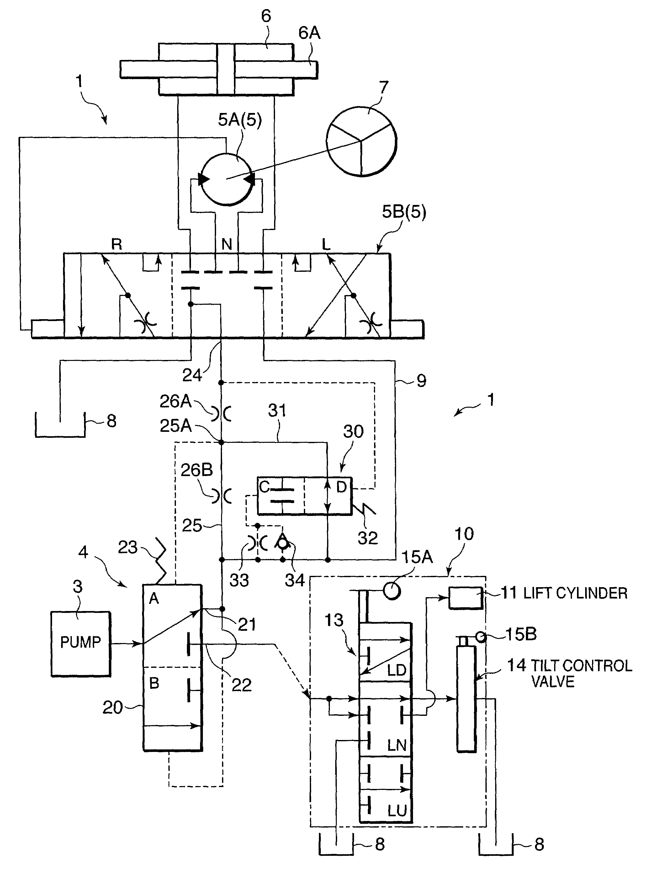
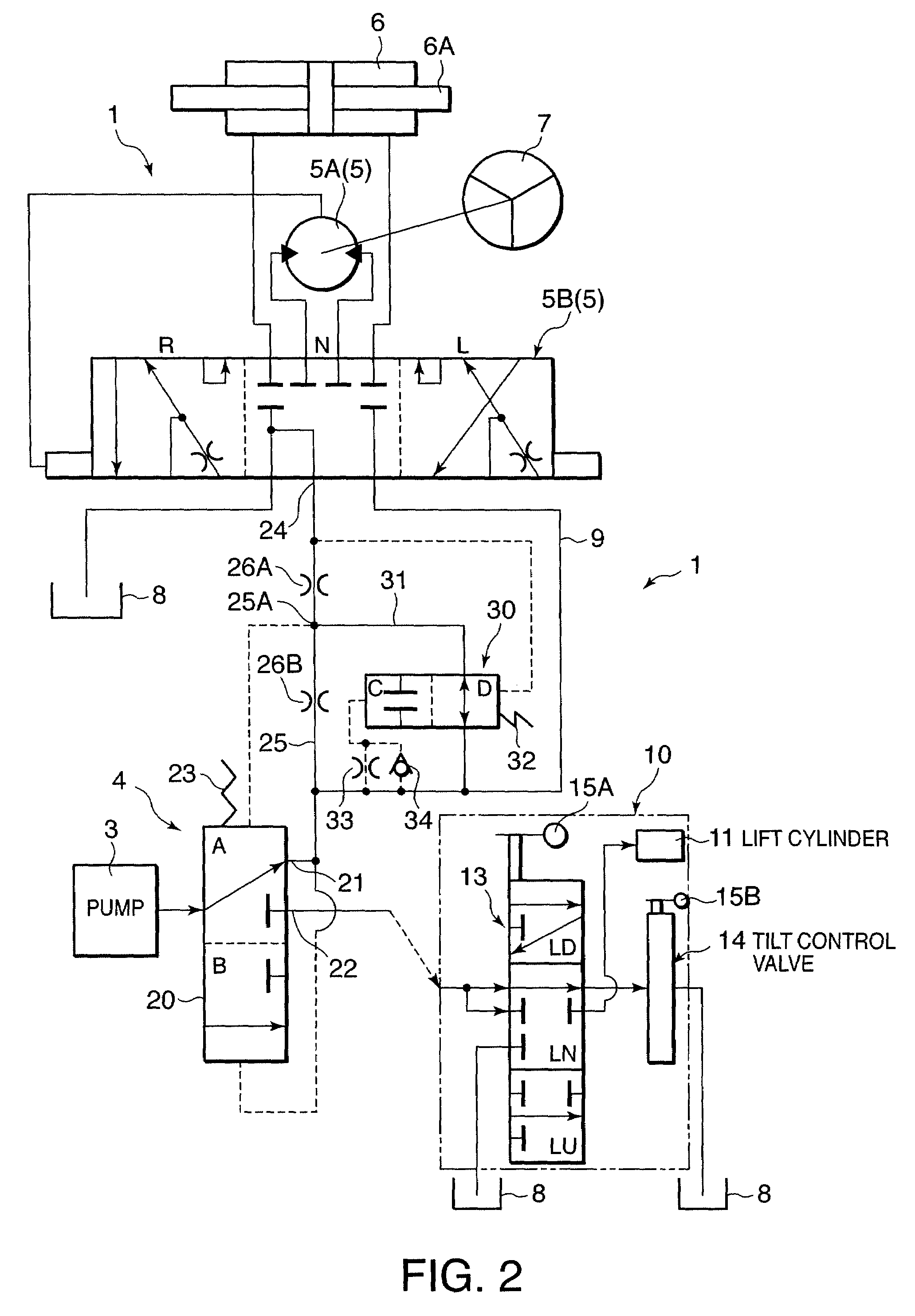
[0073]Referring to FIG. 5, an oil pressure supply circuit according to this invention will be described.

[0074]This embodiment differs from the first embodiment in that the second orifice 26B is integrated into the bypass valve 30 and the bypass valve 30 forms a part of the signal pressure passage 25. With respect to the other components, this embodiment is identical to the first embodiment.

first embodiment

[0075]The bypass valve 30 comprises a damping section C and a connecting section D. The connecting section D simply connects the branch point 25A of the signal pressure passage 25 and the power steering oil passage 9 as in the case of the The damping section C connects the branch point 25A of the signal pressure passage 25 to the power steering oil passage 9 via the second orifice 26B integrated therein. In this embodiment, the connecting section D functions as a bypass passage bypassing the second orifice 26B. By thus integrating the second orifice 26B into the bypass valve 30, the composition of the oil pressure supply circuit is made compact and the implementation cost of the oil pressure supply circuit may be reduced.

third embodiment

[0076]Referring to FIG. 6, this invention will be described.

[0077]In the first and the second embodiments, the bypass valve 30 was disposed in the bypass passage 31 which bypasses the second orifice 26B disposed between the branch point 25A of the signal pressure passage 25 and the power steering oil passage 9. In contrast, in this embodiment, a bypass passage 35 which bypasses the first orifice 26A disposed between the branch point 25A of the signal pressure passage 25 and the load signal port 24 replaces the bypass passage 31 and the bypass valve 30 disposed in the bypass passage 35 in the first and the second embodiments.

[0078]The bypass valve 30 comprises the disconnecting section C and the connecting section D as in the case of the first embodiment. The power steering pressure PS in the power steering oil passage 9 is applied to an end of the valve spool of the bypass valve 30 via the damping orifice 33, and the load signal pressure of the load signal port 24 and the biasing fo...


PUM


Abstract

A priority flow rate control valve (4) increases a distribution ratio of pressurized oil to a power steering device (1) of a fork-lift track via a power steering oil passage (9) as a differential pressure between a power steering pressure (PS) in the power steering oil passage (9) and a pilot pressure (LS) decreases. A load signal port (24) which outputs a pressure indicative of a load exerted on the power steering device (1) and the power steering oil passage (9) are connected via two orifices (26A, 26B), and the pilot pressure (LS) pressure is extracted from a point between the two orifices (26A, 26B). By providing a bypass passage (31, 35) which bypasses one of the two orifices (26A, 26B) and a bypass valve (30) which opens and closes the bypass passage (26A, 26B), a response of the priority flow rate control valve (4) can be increased temporarily.

Description

FIELD OF THE INVENTION[0001]This invention relates to an oil pressure supply circuit used in the steering and cargo handling of an industrial vehicle such as a fork-lift truck.BACKGROUND OF THE INVENTION[0002]U.S. Pat. No. 4,759,182 and JP 2004-196110A published by the Japan Patent Office in 2004 disclose an oil pressure supply circuit which drives a power steering device and a cargo handling device of a fork-lift truck using a single oil pump.[0003]In both prior art circuits, a priority flow rate control valve is provided for distributing pressurized oil from the oil pump to the power steering device preferentially and distributing excess oil to the cargo handling device. For this purpose, a load pressure on the power steering device is caused to act on a valve spool of the priority flow rate control valve via a pilot passage as a pilot pressure and a distribution ratio of pressurized oil to the power steering device is increased as the pilot pressure increases.[0004]The pilot pres...

Claims


Application Information

Patent Timeline
Patent Type & Authority Patents(United States)
IPC IPC(8): F15B13/06F16D31/02
CPCB66F9/22B62D5/075
Inventor KOORIYAMA, MASAYUKI
Owner NISSAN FORKLIFT CO LTD
Why Eureka
Try Eureka