Power delivery over ethernet cables

a technology of power supply and ethernet cable, applied in the field of telecommunications, to achieve the effect of increasing the power of the powered devi

Active Publication Date: 2009-10-13
CISCO TECH INC
View PDF101 Cites 70 Cited by
  • Summary
  • Abstract
  • Description
  • Claims
  • Application Information

AI Technical Summary

Benefits of technology

[0005]Important technical advantages of certain embodiments of the present invention include increased power to powered devices. Certain powered devices, such as wireless communication hubs or docking stations, may be able to make use of more power than provided by conventional power delivery systems. Certain embodiments of the present invention provide increased power for such applications.

Problems solved by technology

However, as telecommunication devices adapt to meet new communication demands, such devices may have different power needs, which may include the need for additional power.

Method used


Image

  • Power delivery over ethernet cables
  • Power delivery over ethernet cables

Examples


Embodiment Construction

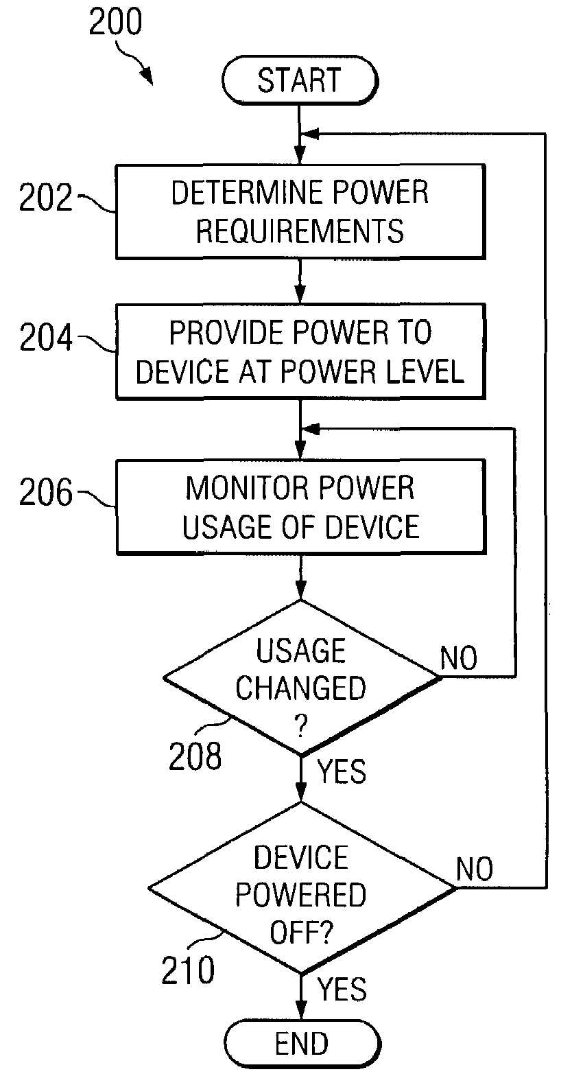
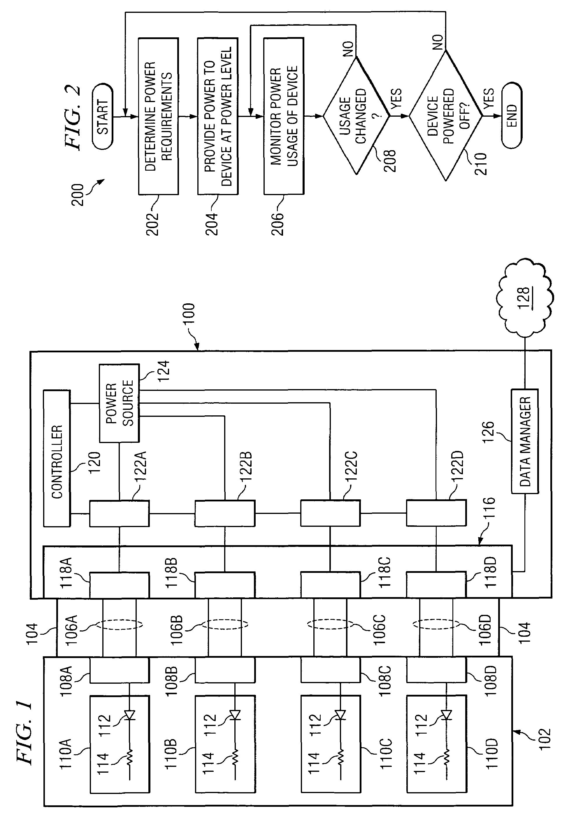
[0012]FIG. 1 illustrates a power delivery system 100 for delivering power to one or more powered devices 102 using Ethernet grade cables, such as Ethernet cables 104. Ethernet cable 104 is any suitable cable set, such as category 3, 4, or 5 cable, used to communicate information using the Ethernet protocol to powered device 102, such as 10 / 100BaseT Ethernet cable. Power delivery system 100 provides power to powered device 102 using up to all four of the pairs 106 (collectively referring to pairs 106A, 106B, 106C, and 106D) in Ethernet cable 104. In one embodiment, more than one pair 106 may be used by providing power through a plurality of ports each coupled to a particular pair 106. In one embodiment, more than one pair 106 may be used by providing power through a port coupled to multiple pairs 106. This may provide advantages over conventional systems that provide power to powered devices using only two pairs of the Ethernet cable at a time, such as those described by the standard...


PUM


Abstract

A method for power delivery comprises coupling an Ethernet cable comprising four wire pairs to a power delivery system and providing power to a powered device on all of the wire pairs. A power delivery system includes an interface operable to couple to an Ethernet cable comprising four wire pairs and a controller operable to provide power to a powered device on all of the wire pairs.

Description

TECHNICAL FIELD OF THE INVENTION[0001]This invention relates in general to telecommunications, and more particularly to a method and system for improved power delivery over Ethernet cables.BACKGROUND OF THE INVENTION[0002]Numerous powered devices utilize power delivered over four-pair Ethernet cables. IEEE has issued a standard, IEEE 802.3af, that specifies methods of power delivery over Ethernet. In particular, the standard describes the use of two of the four pairs to deliver power to a powered device. However, as telecommunication devices adapt to meet new communication demands, such devices may have different power needs, which may include the need for additional power. Accordingly, an improved method for delivering power to powered devices would be useful.SUMMARY OF THE INVENTION[0003]In accordance with one embodiment of the present invention, a method for power delivery includes coupling an Ethernet cable comprising four wire pairs to a power delivery system and providing powe...

Claims


Application Information

Patent Timeline
Patent Type & Authority Patents(United States)
IPC IPC(8): G06F1/00G06F1/30G06F1/32H04L12/10
CPCG06F1/3203H04L12/10G06F17/3087G06F16/9537Y10S707/99937
Inventor SCHINDLER, FREDERICK R.DIAB, WAEL WILLIAM
Owner CISCO TECH INC
Why Eureka
Try Eureka