
Sensor for measurement for wet and dry fingers

Active Publication Date: 2009-10-20
IDEX BIOMETRICS ASA
View PDF18 Cites 19 Cited by
  • Summary
  • Abstract
  • Description
  • Claims
  • Application Information

AI Technical Summary

Benefits of technology

[0012]It is thus an object of this invention to provide a sensor which avoids the abovementioned problems and relates to a method for assuring adequate signal levels and image quality for both wet and dry fingers, despite these large differences in conductivity. This is obtained by a sensor as stated above and which is characterized in that it comprises a number of conductive structures at or directly below the sensor surface, sai

Problems solved by technology

One problem for capacitive fingerprint sensors is that the finger conductivity (both resistive and AC capacitive) vary strongly with the humidity of the finger.
Another problem may be that the ridge itself is not perfectly smooth, resulting in ridge areas where there is a shallow air gap between the ridge and the sensor surface.
For wet fingers, where water or saline (sweat) fill the valleys, the problem is mainly that the saline is even more conductive than the stem corneum.
With the described capacitive measuring technique this gives a high signal for both valleys and ridges, so that it is difficult to separate the two.
Such an image does not easily lend itself to software algorithms aimed at fingerprint recognition.
This principle however has the same drawback: Sweat-filled valleys will give approximately the same signal as a fingerprint ridge, and the two will be practically impossible to distinguish.

Method used


Image

  • Sensor for measurement for wet and dry fingers
  • Sensor for measurement for wet and dry fingers
  • Sensor for measurement for wet and dry fingers

Examples


Embodiment Construction

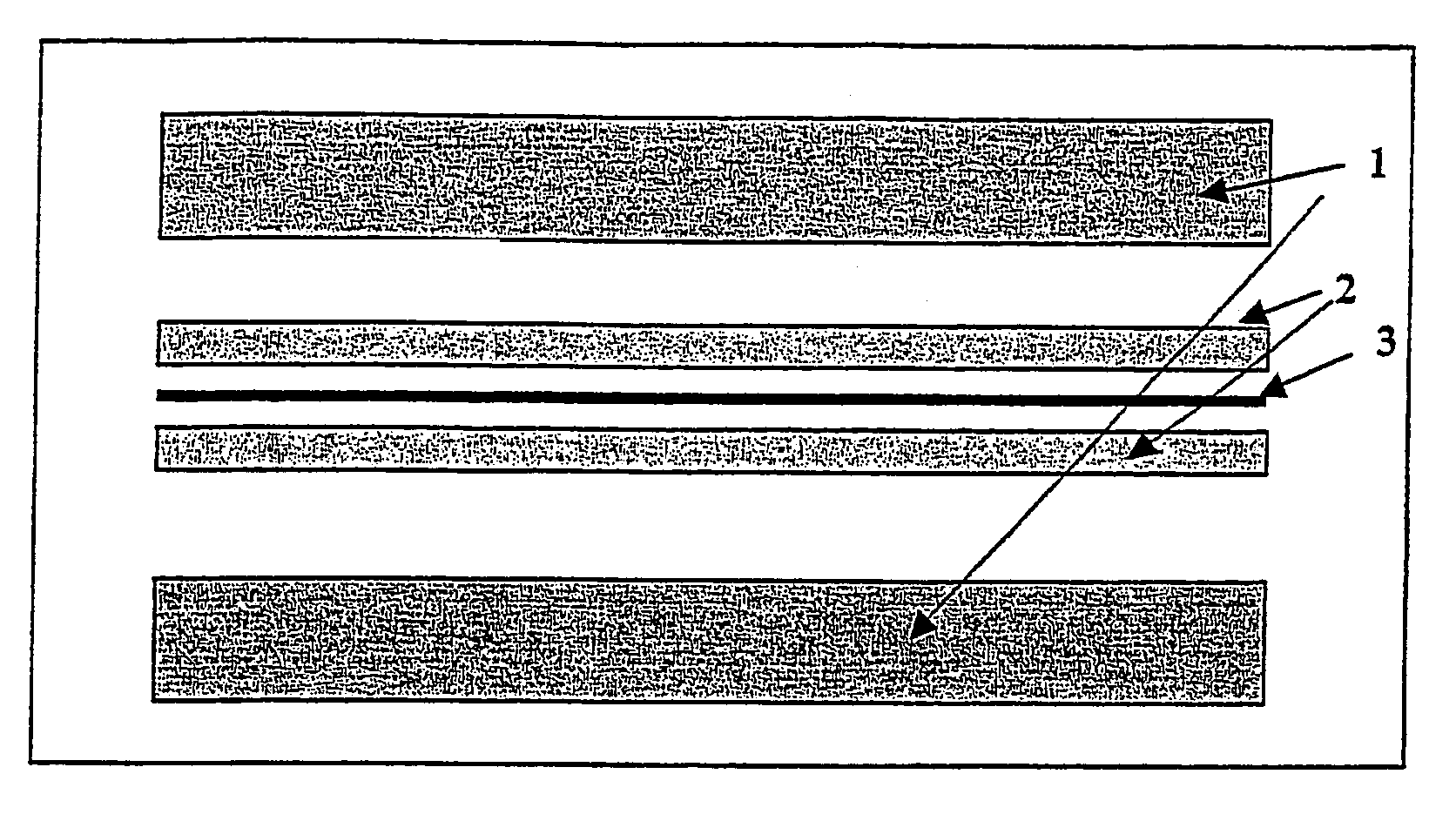
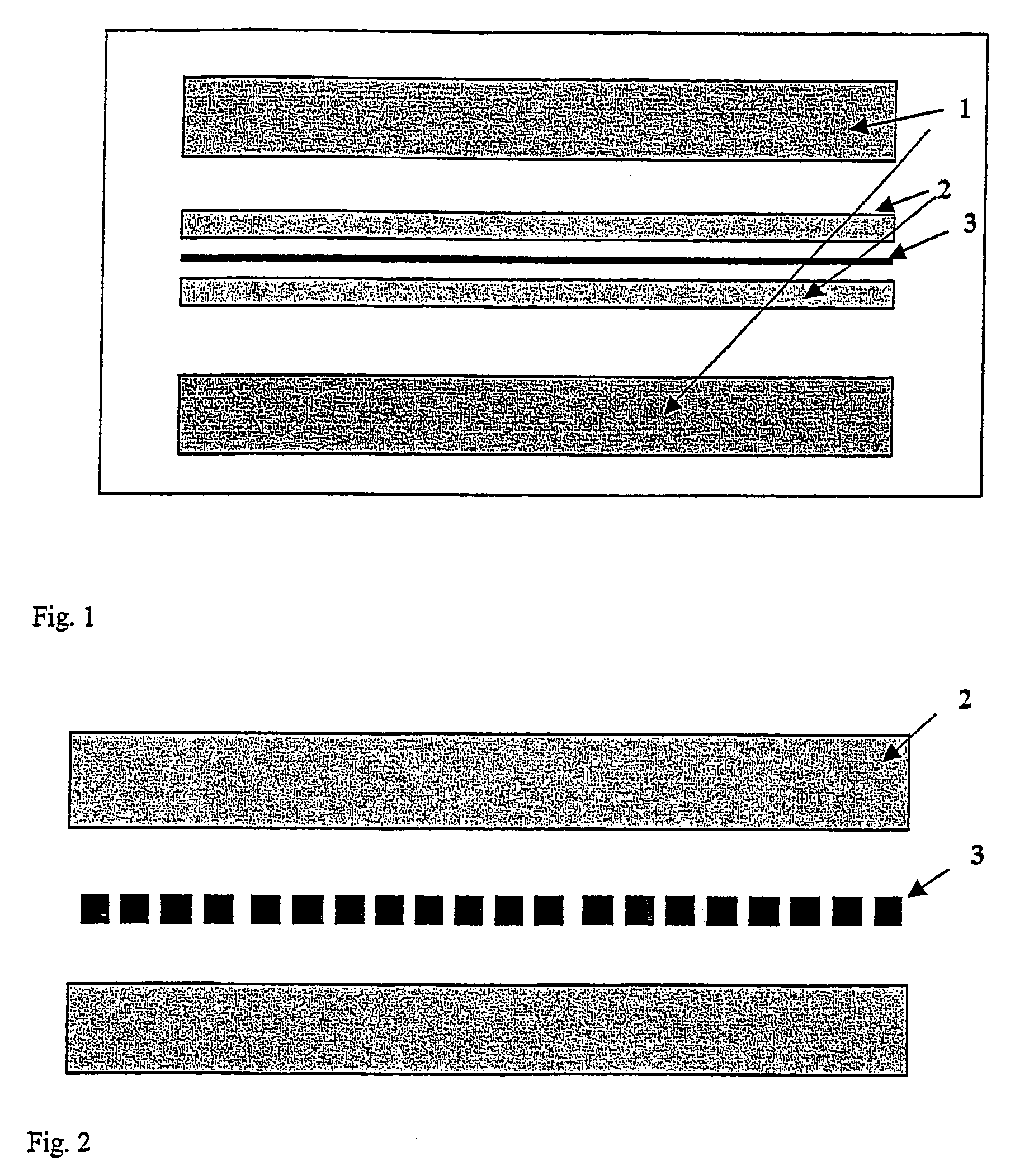
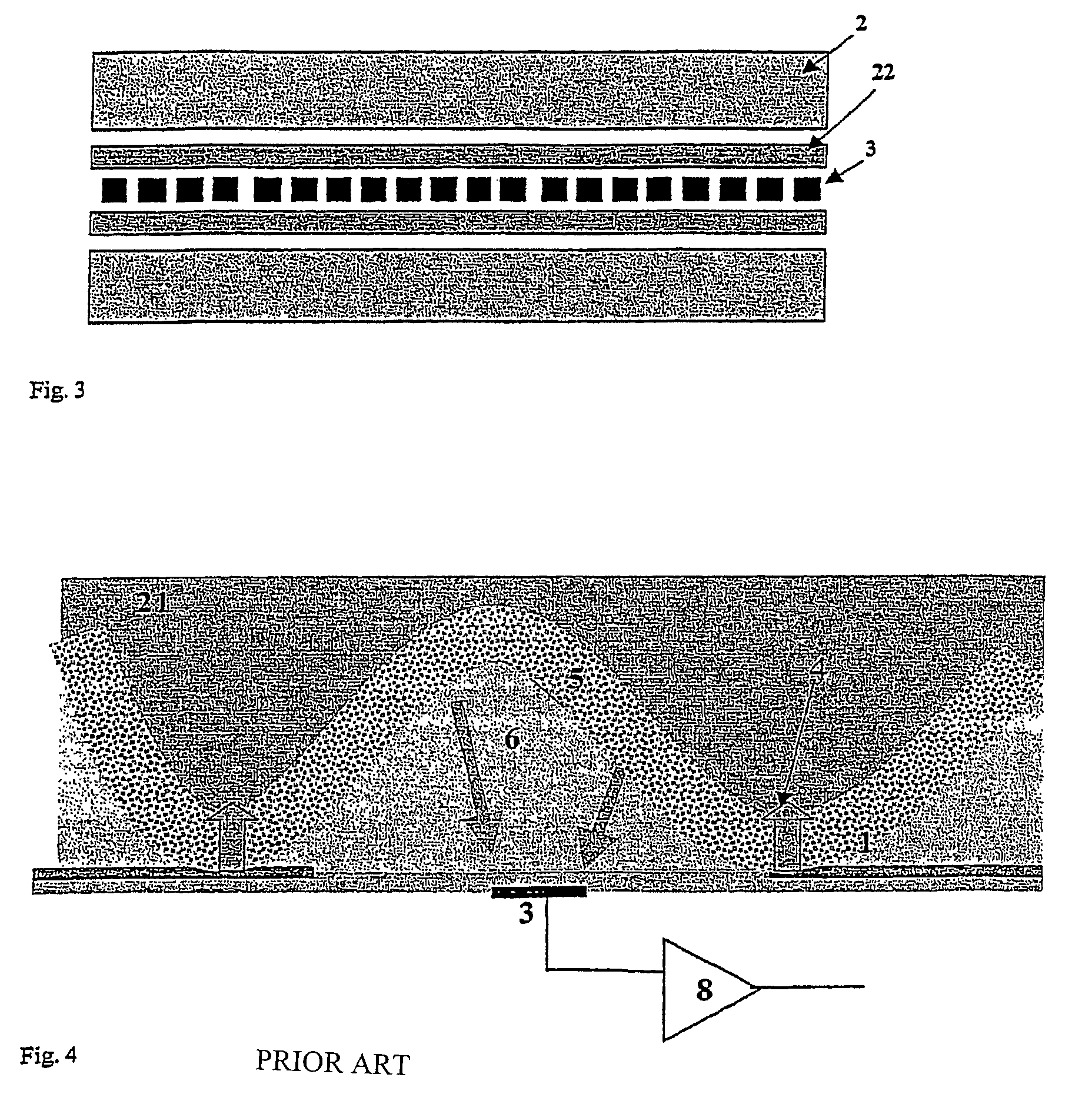
[0028]FIG. 1 describes an embodiment of the invention comprising a sensor surface equipped with a number of sensor pads 3 for capacitance measurements, and at least two electrodes 1,2 that may either be located on the sensor surface or be external to this. The illustrated fingerprint sensor thus preferably is an essentially linear sensor array as described in the abovementioned international patent applications, especially WO 01 / 94902, and may, in addition to the array 3 of sensor elements, include velocity sensors (not shown in the drawings) for measuring the velocity of the finger and thus together with the measured characteristic of the finger surface reconstitute an image of the fingerprint. Other methods for reconstituting the image may, however, also be contemplated, e.g. as in the abovementioned U.S. Pat. No. 6,289,114, in which overlapping images from several sensor lines are used to reconstitute the image.

[0029]In the drawings one electrode, the outer electrode or drive ele...


PUM


Abstract

A sensor device for performing measurements on an at least partially conductive surface includes a number of conductive structures at or directly below the sensor surface. The conductive structures consist of at least one stimulation or current sink electrode and a number of sensor elements coupled to interrogation electrodes in an electronic circuit for measuring impedance between the electrodes and the stimulation electrode. The sensor device also includes at least one additional clamping electrode positioned in the vicinity of the sensor elements and coupled to a chosen voltage.

Description

CROSS REFERENCE TO RELATED APPLICATIONS[0001]This application is a 35 U.S.C. § 371 National Phase Entry Application from PCT / NO02 / 00465, filed Dec. 6, 2002, and designating the U.S.BACKGROUND OF THE INVENTION[0002]1. Field of the Invention[0003]This invention relates to sensor device for performing measurements on an at least partially conductive surface, specially a sensor geometry to facilitate AC capacitive fingerprint measurements on wet and dry fingers.[0004]2. Description of the Related Art[0005]AC capacitive fingerprint sensors are known e.g. firm international patent applicaton WO 98 / 58342. These sensors utilize an array of capacitive sensor elements (sensor pads) to capture a fingerprint image from a finger which is held onto or pulled across the sensor surface. Capacitive fingerprint sensors roughly divide into two categories: matrix sensors, where the fingerprint is placed onto a two-dimensional sensor surface, and scanners or sweep sensors, where the user is required to ...

Claims


Application Information

Patent Timeline
IPC IPC(8): G06K9/00G06K9/20G01B7/28A61B5/117G06T1/00
CPCG06K9/0002G06V40/1306
Inventor NYS.AE BUTTED.THER, JONRIISN.AE BUTTED.S, KNUTDYVE, LEGAL REPRESENTATIVE, INGVILD JUVKAMMARTINSEN, ORJAN G.MOSTAD, GEIRCHRISTIE, NICOLAI W.PEDERSEN, RUNE
Owner IDEX BIOMETRICS ASA
Learn More