Adjusting device for a hand-held tool

a technology for adjusting devices and hand-held tools, which is applied to pliers, spanners, wrenches, etc., can solve the problems of not providing the positive instantaneous action required, requiring manual effort in addition to two-handed operation, and requiring two-handed operation. , to achieve the effect of simple and effective, facilitates the release of clamping pressur

Inactive Publication Date: 2009-10-27
FRANCIS INT
View PDF9 Cites 12 Cited by
  • Summary
  • Abstract
  • Description
  • Claims
  • Application Information

AI Technical Summary

Benefits of technology

[0007]An advantage of the present invention is that the adjusting device obviates the need for dual-handed operation.
[0008]Another advantage of the present invention is that the adjusting device enables the user to apply added clamping pressure single-handedly to a contact member in contact with a work piece.
[0009]A further advantage of the present invention is that the adjusting device facilitates release of the clamping pressure when desired to disengage the contact member from the work piece.
[0010]Yet a further advantage of the present invention is that the adjusting device provides a simple and effective means of switching the clamping action from one end to another of a hand tool device with the use of one actuating member.
[0011]Still a further advantage of the present invention is that the piston of the adjusting device can be used to displace a pivotable and / or slidable contact member for clamping or holding a work piece therewith, such as in pliers and the like, or an open-face wrench or any other type of hand tools.
[0012]A further object of the present invention is to provide a hand tool device which affords positive actuation of the valving to open and close the same.

Problems solved by technology

Whilst the hand tool device of this prior art functions adequately well, it has been found in practice that the resilient loading of the button can deteriorate with time occasioning response delay thus causing somewhat inefficient operation of the tool and not providing the positive instantaneous action required.
Furthermore, it requires two-handed operation and manual effort in addition to the fluid, e.g. hydraulic, force applied to the contact member.

Method used


Image

  • Adjusting device for a hand-held tool
  • Adjusting device for a hand-held tool
  • Adjusting device for a hand-held tool

Examples


first embodiment

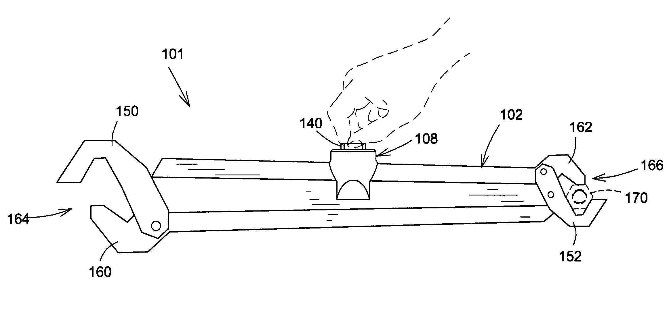
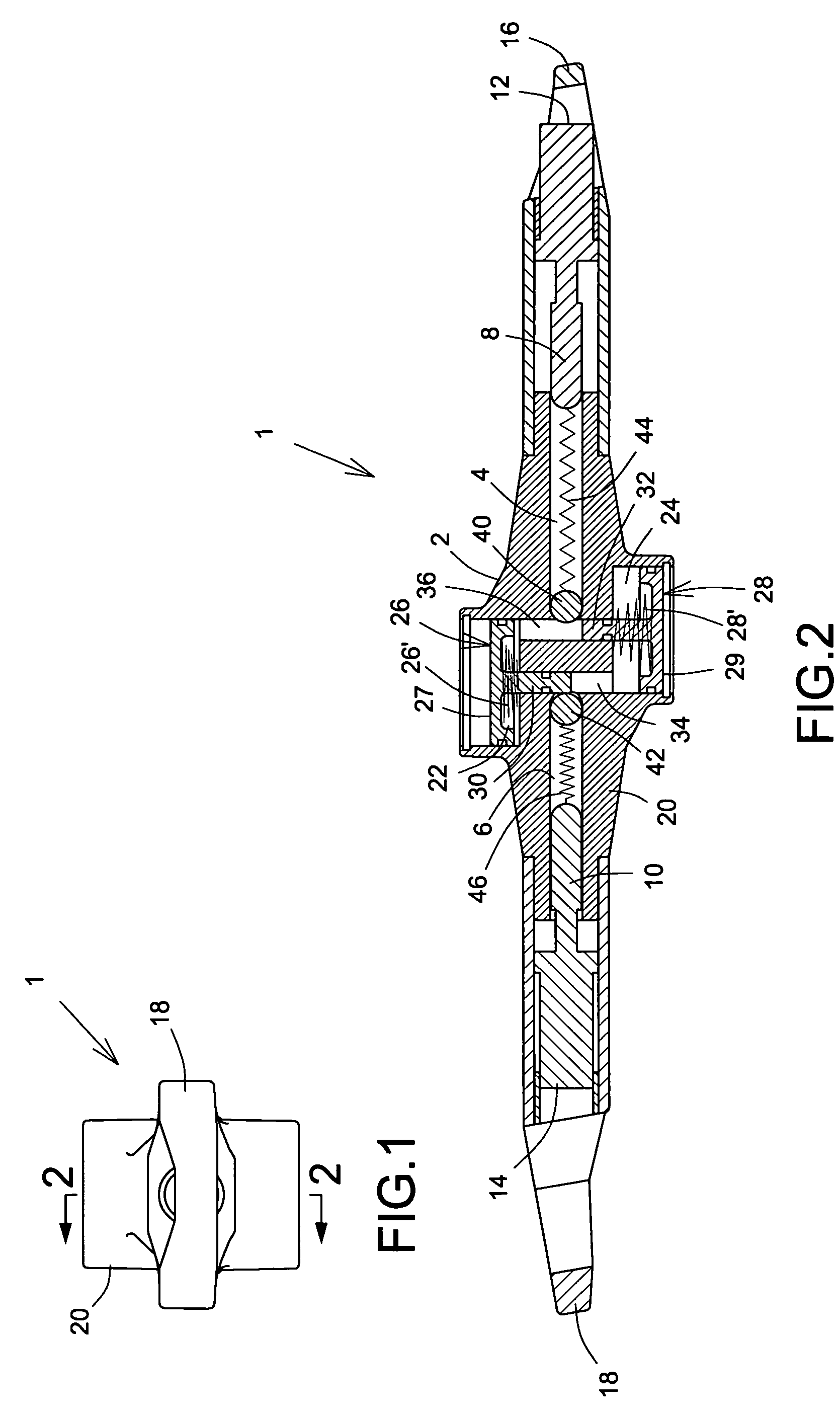
[0079]In operation of the first embodiment, one end ring 16 is located over a work piece 3 by a user and the relatively lower plunger 28 (as shown in the drawing) is depressed by the user the oil from the reservoir 24 to become pressurized and in so doing the ball valve 42 is lifted off its seating against the action of the spring 46 thus allowing the oil to enter the cylinder 6 to extend the contact member 14 into the ring space. At the same time the stem 32 of the plunger 28 contacts the opposite ball valve 40 to lift it from its seating thus allowing egress of oil from the cylinder 4 and releasing the contact member 12. At the same time the oil escaping from the cylinder 4 pushes the plunger 26 to a starting position within the respective reservoir 22. Furthermore, release of manual pressure from the plunger 28 allows the valve 42 to become reseated under the action of the spring 46, thus locking the contact member 14 onto the work piece. When the tool is to be released from its ...

second embodiment

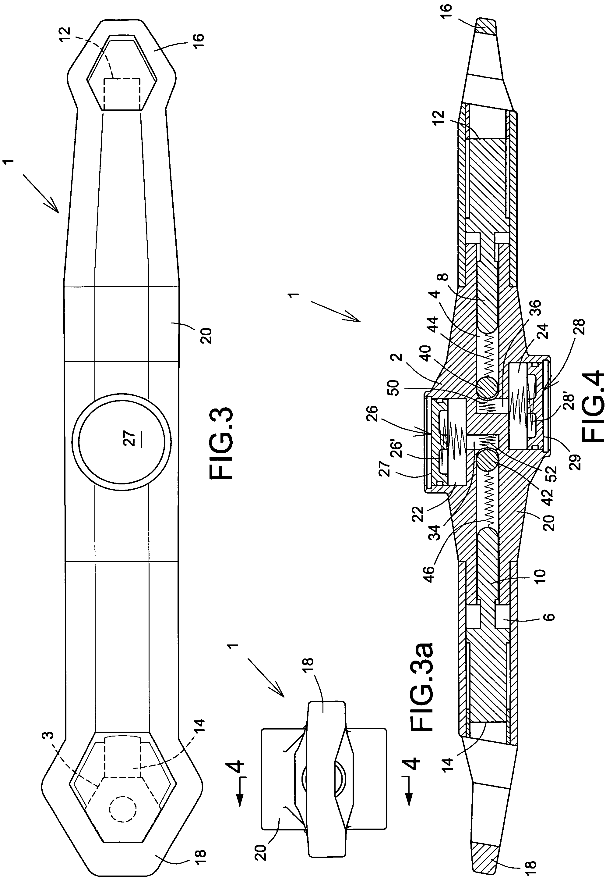
[0083]In this second embodiment, when it is desired to apply clamping pressure to a work piece 3 registering within one of the rings 16, 18 the appropriate plunger 26, 28 is operated to push oil from the reservoir 22, 24 into the fluid-filled cylinder 4, 6 and initiate displacement of the contact member 12, 14. Once the member 12, 14 contacts the work piece, the user stops depressing the plunger 26, 28 and starts rotating the tool around the work piece to pressurize the oil in the respective reservoir 22, 24. With the increasing pressure within the relevant cylinder, the ball valve reseats under the action of the oil pressure to lock the oil within the cylinder. However, once pressure on the work piece is removed the secondary spring 50, 52, which is of greater strength than the main spring 44, 46, overcomes the resistance of the main spring and lifts the valve 40, 42 off its seating to allow back flow of the oil into the reservoir 22, 24.

[0084]In this second embodiment, the contact...

third embodiment

[0085]Referring now to FIGS. 5, 6 and 6a, an adjusting hand tool device comprises similar features to those shown in FIGS. 3, 3a and 4 with the exception of the control block 20 which houses a single reservoir 20 with its associated spring-loaded plunger 26 which carries a stem 30 of hexagonal cross section (any other non-circular shape could obviously be considered without departing from the scope of the present invention) as can be seen more distinctly in FIG. 6a, and is rotatably moveable within the generally cylindrical guide bore 34′. A selector element in the form of a disc 60 sealably engages on the stem 30 and is provided with blanking zone 62 and a cut-out 64 which latter is shown in FIGS. 6 and 6a registering with a bore 66 extending from the reservoir 22 and opening into the end of the cylinder 4, a similar bore 68, shown as being blocked by the disc 60, also extends from the reservoir 22 to open into the end of the cylinder 6. The ball valves 40, 42 are spring-loaded on ...


PUM


Abstract

A hand tool device incorporates a fluid operated mechanism actuable by a plunger pressurizing a reservoir to force fluid past a resiliently biased valve to a fluid filled cylinder accommodating a piston carrying a contact member for clamping a work piece in the manner of an adjustable wrench or pliers. Continued operation of the plunger increases the pressure applied to the work piece.

Description

CROSS REFERENCE TO RELATED APPLICATION[0001]The present invention is a Continuation-In-Part of U.S. patent application Ser. No. 11 / 802,600 filed on May 24, 2007, now abandoned, and which is incorporated herein by reference. Benefit of U.S. Provisional Application for Patent Ser. No. 60 / 960,713 filed on Oct. 11, 2007, is hereby claimed.FIELD OF THE INVENTION[0002]The present invention relates to hand tool devices, and is more particularly concerned with an adjusting device for hand-held tools, for example wrenches and the like, for applying torque to fixtures or work pieces, such as nuts and bolts.BACKGROUND OF THE INVENTION[0003]In my U.S. Pat. No. 6,973,857 I describe such a hand tool device which incorporates fluid operable contact members which is moveable into alternate clamping positions in relation to a work piece by the actuation of a button. The contact members are carried by pistons sliding within opposed cylinders having at their full bore ends resiliently loaded ball valv...

Claims


Application Information

Patent Timeline
Patent Type & Authority Patents(United States)
IPC IPC(8): B25B13/12B25B13/00B25B7/00
CPCB25B13/28B25B13/12
Inventor ANDERSON, DWAIN
Owner FRANCIS INT
Why Eureka
Try Eureka