Hand-held electric power tool

a power tool and hand-held technology, applied in the direction of portable percussive tools, bulkheads/piles, drilling machines and methods, etc., can solve the problem of requiring a relatively large installation space for switching elements which are displaceable perpendicular to one another

Active Publication Date: 2009-10-27
HILTI AG
View PDF9 Cites 23 Cited by
  • Summary
  • Abstract
  • Description
  • Claims
  • Application Information

AI Technical Summary

Benefits of technology

[0008]This and other objects of the present invention, which will become apparent hereinafter, are achieved, according to the invention, with a hand-held power tool in which the impact mechanism switching means have a swiveling mechanism which can be swiveled by the mode switch between an active position in which the impact mechanism can be activated, and a passive position in which the impact mechanism is deactivated. A swiveling mechanism of this type can be so designed that it occupies the same amount of space, at least predominantly, in different switching positions. Accordingly, the installation space required for the moving impact mechanism switching means is relatively small, which in turn makes possible a more compact manner of constructing the hand-held power tool.
[0009]In a particularly preferred embodiment form, the swiveling mechanism has a switch-side swiveling member which is held so as to be swivelable at a rotary bearing. This swiveling member is movement-coupled with the mode switch and actuates actuating means, depending on whose position the impact mechanism can be switched on and off. A stable swiveling mechanism, which maintains the impact mechanism securely in a selected operating state, can be provided by designing the swiveling member in this way.
[0010]A cam element is advantageously provided at the mode switch, and the switch-side swiveling member and gear unit switching means can be actuated by means of this cam element. The switching positions of the gear unit can accordingly be matched directly to the switching positions of the impact mechanism. In this way, it can be ensured, for example, that a rotational speed that is particularly suitable for the impact mechanism is adjusted when the impact mechanism is switched on.

Problems solved by technology

It is disadvantageous in the known switching device that the switching elements which are displaceable perpendicular to one another require a relatively large installation space.

Method used


Image

  • Hand-held electric power tool
  • Hand-held electric power tool
  • Hand-held electric power tool

Examples


Embodiment Construction

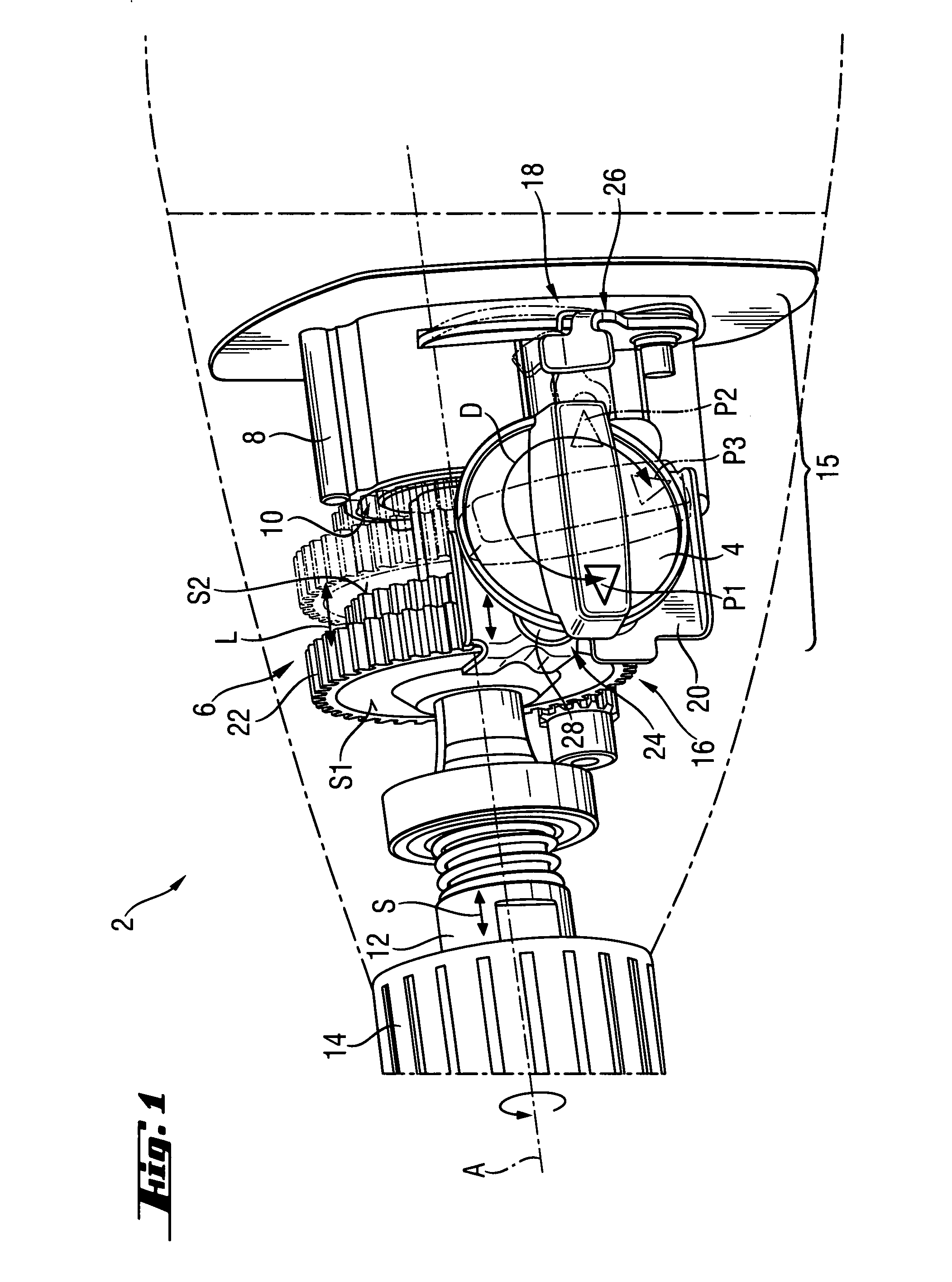
[0028]FIG. 1 shows a front part of a hand-held power tool 2 in the form of a hammer drill. This hand-held power tool 2 has a mode switch 4 by means of which a switching gear unit 6 and an impact mechanism 10 received in an impact mechanism housing 8 can be switched back and forth between different switching stages. The mode switch 4 is constructed as a rotary switch.

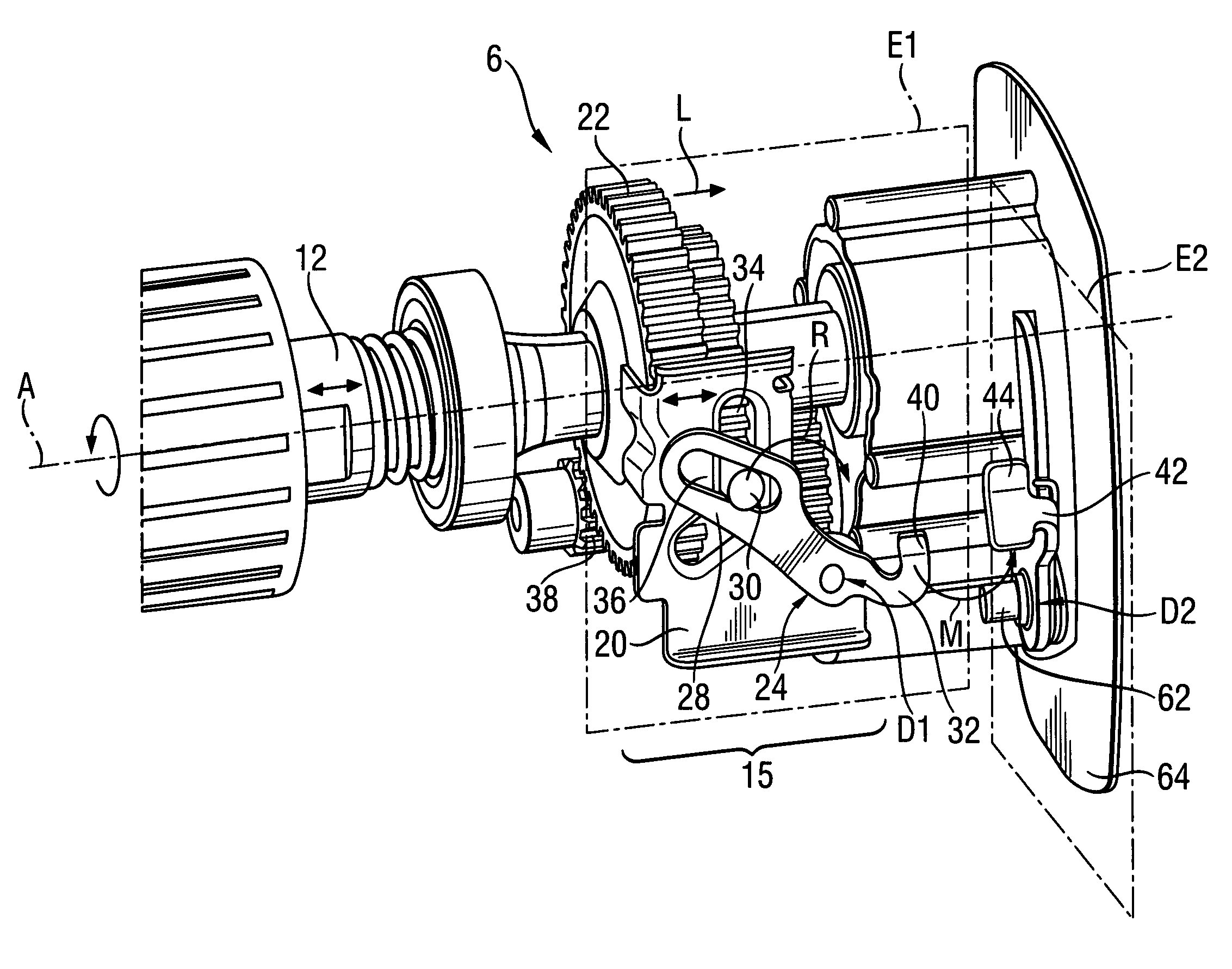
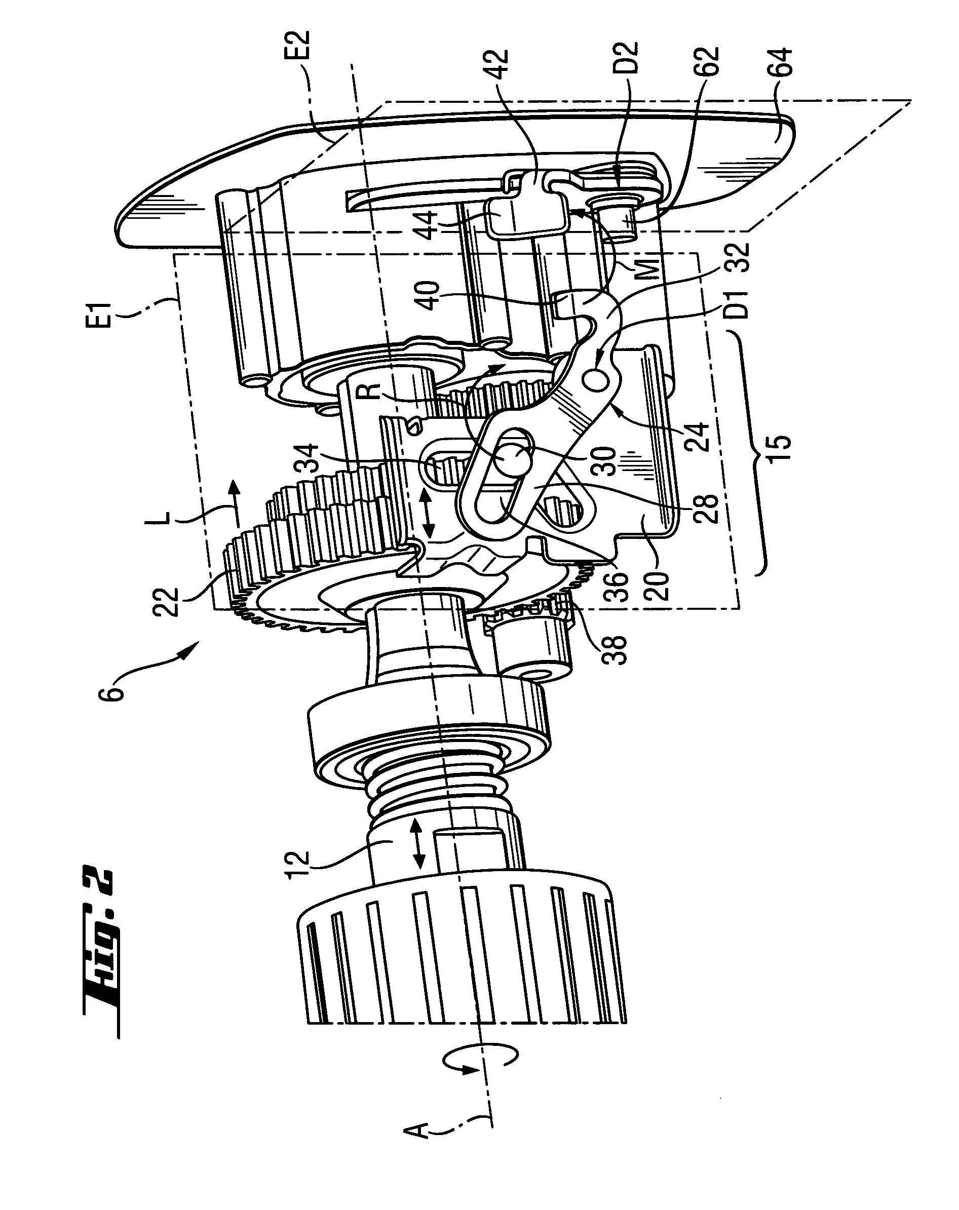
[0029]In this way, a tool spindle 12, at which a tool holder 14 is held, can be driven by the switching gear unit 6 around a work axis A at different rotational speeds, on one hand. On the other hand, recurring pulsed percussive force S can be applied to the tool spindle 12 selectively in addition by means of the impact mechanism 10 along the work axis A. For this purpose, the tool spindle 12 is supported so as to be rotatable and axially displaceable.

[0030]In order to actuate the switching gear unit 6 and the impact mechanism 10 by means of the individual mode switch 4, a switching arrangement, designated in its entiret...


PUM


Abstract

A hand-held electric power tool (2) includes a switching gear unit (6) which has at least two switching stages, including an impact mechanism (10) which can be switched on, and a mode switch (4) with which the switching gear unit (6) can be switched back and forth between the switching stages. The impact mechanism (10) can be switched on and off, and the mode switch (4) is movement-coupled with a gear unit switching mechanism (16) of the switching gear unit (6) and with an impact mechanism switching mechanism (18) of the impact mechanism (10). The impact mechanism switching mechanism (18) has a swiveling mechanism which can be swiveled by the mode switch (4) between an active position, in which the impact mechanism (10) can be activated, and a passive position in which the impact mechanism (10) is deactivated.

Description

BACKGROUND OF THE INVENTION[0001]1. Field of the Invention[0002]The invention relates to an electric hand-held power tool having a switching gear unit having at least two switching stages. Further, the hand-held power tool has an impact mechanism which can be switched on and off selectively, and a mode switch by means of which the switching gear unit can be switched back and forth between the switching stages and the impact mechanism can be switched on and off. To this end, the mode switch is movement-coupled with gear unit switching means of the switching gear unit and with impact mechanism switching means of the impact mechanism.[0003]2. Description of the Prior Art[0004]In hand-held power tools of the kind mentioned above, the various gear unit switching stages and the impact mechanism can be switched by a single movement of the hand. This enables a more comfortable operation and facilitates manufacture of the device.[0005]DE 10 2004 057 686 A1 discloses a switching device for an...

Claims


Application Information

Patent Timeline
Patent Type & Authority Patents(United States)
IPC IPC(8): E21B6/00E21B6/04
CPCB25D16/006B25D2211/006B25D2216/0038B25D2216/0023B25D2211/064
Inventor ERHARDT, JOCHEN
Owner HILTI AG
Why Eureka
Try Eureka