Stabilizing a substrate using a vacuum preload air bearing chuck

a vacuum preloading and air bearing technology, applied in the direction of mechanical means, instruments, manufacturing tools, etc., can solve the problems of limited bandwidth, reduced depth of focus, reduced spot size of “probe”, etc., and achieve the effect of preventing deformation of thin and flexible wafers

Active Publication Date: 2009-10-27
KLA TENCOR TECH CORP
View PDF31 Cites 121 Cited by
  • Summary
  • Abstract
  • Description
  • Claims
  • Application Information

AI Technical Summary

Benefits of technology

[0017]In certain embodiments of the present invention, by contrast, one or more vacuum ports may be distributed across a surface of a chuck to disperse the vacuum force. FIG. 1 is a cross-sectional view of a substrate processing apparatus 100 of a preferred embodiment of the present invention. As shown in FIG. 1, the substrate processing apparatus 100 includes a chuck 112 having a surface 106. The surface 106 includes one or more gas flow openings 113 configured to provide a flow of gas 110 to the surface 106 and one or more vacuum channels 111 distributed across the surface 106. The gas flow openings may be coupled to a source of the gas 110 by a network of gas channels in the body of the chuck 112. A porous material 107 may optionally be disposed between the gas flow openings 113 and the surface 106 to diffuse the flow of gas. For example, the surface 106 can be made of a porous material, preferably sintered metal powder, such as sintered Nickel powder. Alternatively, the surface 106 can be a solid metal or ceramic surface with holes that communicate with the network of gas channels. The vacuum channels 111 are configured to permit vacuum 108 to be drawn therethrough. By way of example, the vacuum channels 111 may be coupled to a source of vacuum (e.g., a vacuum pump) by a network of channels in the body of the chuck 112. A substrate 102, such as a reticle or a semiconductor wafer, can freely float on a thin layer of pressurized gas layer 104 on top of the chuck 112 without being in contact with the chuck surface 106. The substrate 102 is simultaneously vacuumed down towards the chuck surface 106 by a vacuum preload exerted through the vacuum channels 111 to provide a high degree of rigidity that stabilizes the wafer during high speed rotation.
[0021]Referring again to FIG. 2A, the substrate processing apparatus 100 of the present invention may also include a scanning tool 120 proximate the front surface 101 of the substrate 102. The tool may perform scanning measurement of the front surface 101 of the substrate as the substrate rotates. The scanning tool 120 may include a probe 122 coupled to a scanning mechanism 124. The probe may be an optical tool, e.g., an optical microscope, such as laser or other light source, optical imaging system, wafer inspection tool, or wafer metrology tools such as a reflectometer and / or ellipsometer. The scanning mechanism 124 may scan the probe 122 across a front surface 101 of the substrate 102 in a direction substantially parallel to a plane of rotation of the substrate. With such a configuration, the probe may be scanned relative to the front surface 101 of the substrate 102 in a spiral pattern. Since the chuck 112 does not rotate relative to the probe 122, variations in the height of the chuck surface that are transferred to the substrate tend to remain relatively stationary with respect to the chuck 112 even at high-speed rotation of the substrate. Consequently, the variation in the depth of focus depends on the scanning speed of the probe and not on the much higher tangential velocity of the front surface 101. Thus, the probe 122 having a relatively low bandwidth auto focus may maintain focus on the front surface 101 without modification.
[0028]Distribution of the vacuum channels across the surface of the vacuum chuck tends to disperse the chucking force and prevents deformation of thin and flexible wafers that might otherwise result if all of the vacuum were applied at a single location. FIGS. 6A-6F are top views illustrating a few of many possible different distributions of the vacuum channels and the gas flow openings in the surface of the chuck. By way of non-limiting example, in FIG. 6A, the surface of a chuck 602 includes vacuum holes 604 arranged in a rectangular grid pattern and a more or less uniformly distributed air flow area 606. The air flow area 606 may be provided through use of a rectangular grid of gas inlets and a porous material, e.g., as shown in FIG. 1. In FIG. 6B, the surface of a chuck 608 includes a series of alternating concentric annular vacuum channels 610 and annular gas flow areas 612 between the channels. The gas flow areas 612 may be provided through use of annular patterns of gas inlets and a porous material. In FIG. 6C, the surface of a chuck 618 includes vacuum holes 616 arranged in a series of concentric ring patterns and a gas flow area 614. The gas flow area 618 may be provided through use of any suitable pattern of gas inlets and a porous material. FIG. 6D, illustrates an example of a chuck 620 that combines the features of FIG. 6B and FIG. 6C. Specifically, a surface of the chuck 620 may include one or more concentric annular vacuum channels 622. Gas flow openings 624 are arranged in concentric patterns between the vacuum channels 622. The gas flow openings 624 may include a central opening aligned with an axis of symmetry of the concentric vacuum channels 622.

Problems solved by technology

However, as the spot size of the “probe” reduces due to the requirement of improved sensitivity, the depth of focus reduces.
Auto focus systems typically have limited bandwidths, which make it difficult to track wafer height variations at high rotational speeds.
In addition, contact between the back surface of the wafer and the chuck surface may generate numerous particles, which can contaminate the wafer above an acceptable level and reduce the yield of usable devices from the wafer.
Thus, vertical wafer rotation would probably require substantial and expensive reconfiguration, re-engineering and redesign and perhaps replacement of semiconductor wafer tools.

Method used


Image

  • Stabilizing a substrate using a vacuum preload air bearing chuck
  • Stabilizing a substrate using a vacuum preload air bearing chuck
  • Stabilizing a substrate using a vacuum preload air bearing chuck

Examples


Embodiment Construction

[0015]Although the following detailed description contains many specific details for the purposes of illustration, anyone of ordinary skill in the art will appreciate that many variations and alterations to the following details are within the scope of the invention. Accordingly, the exemplary embodiments of the invention described below are set forth without any loss of generality to, and without imposing limitations upon, the claimed invention.

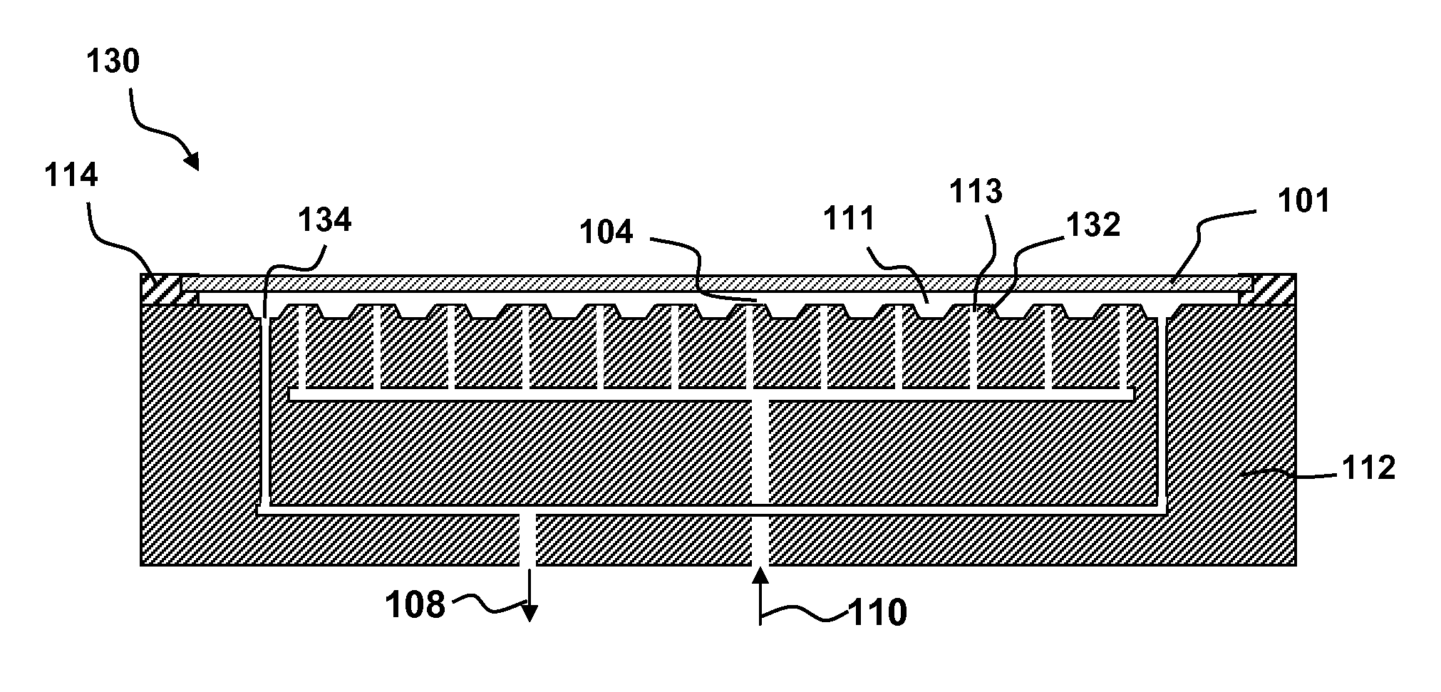
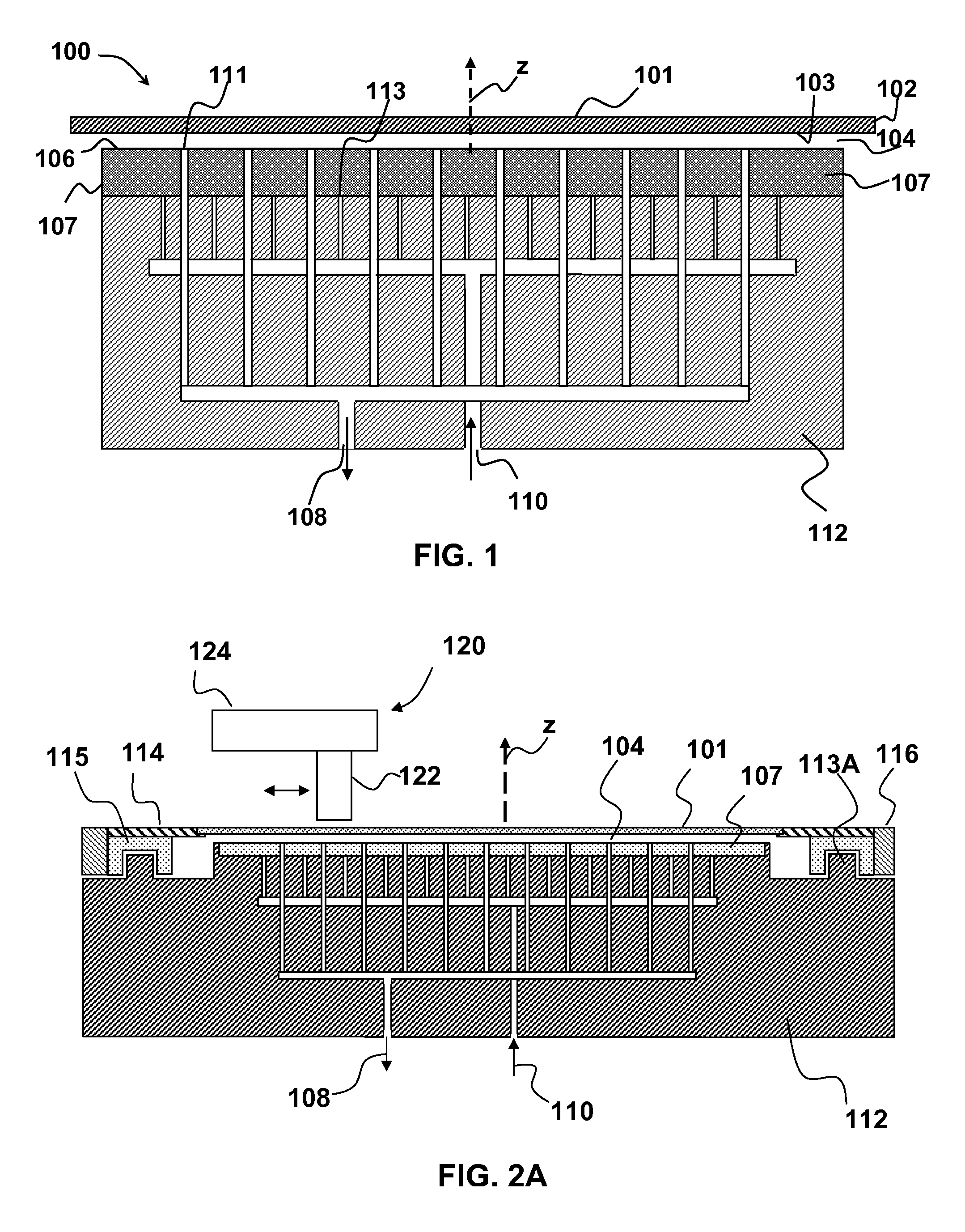
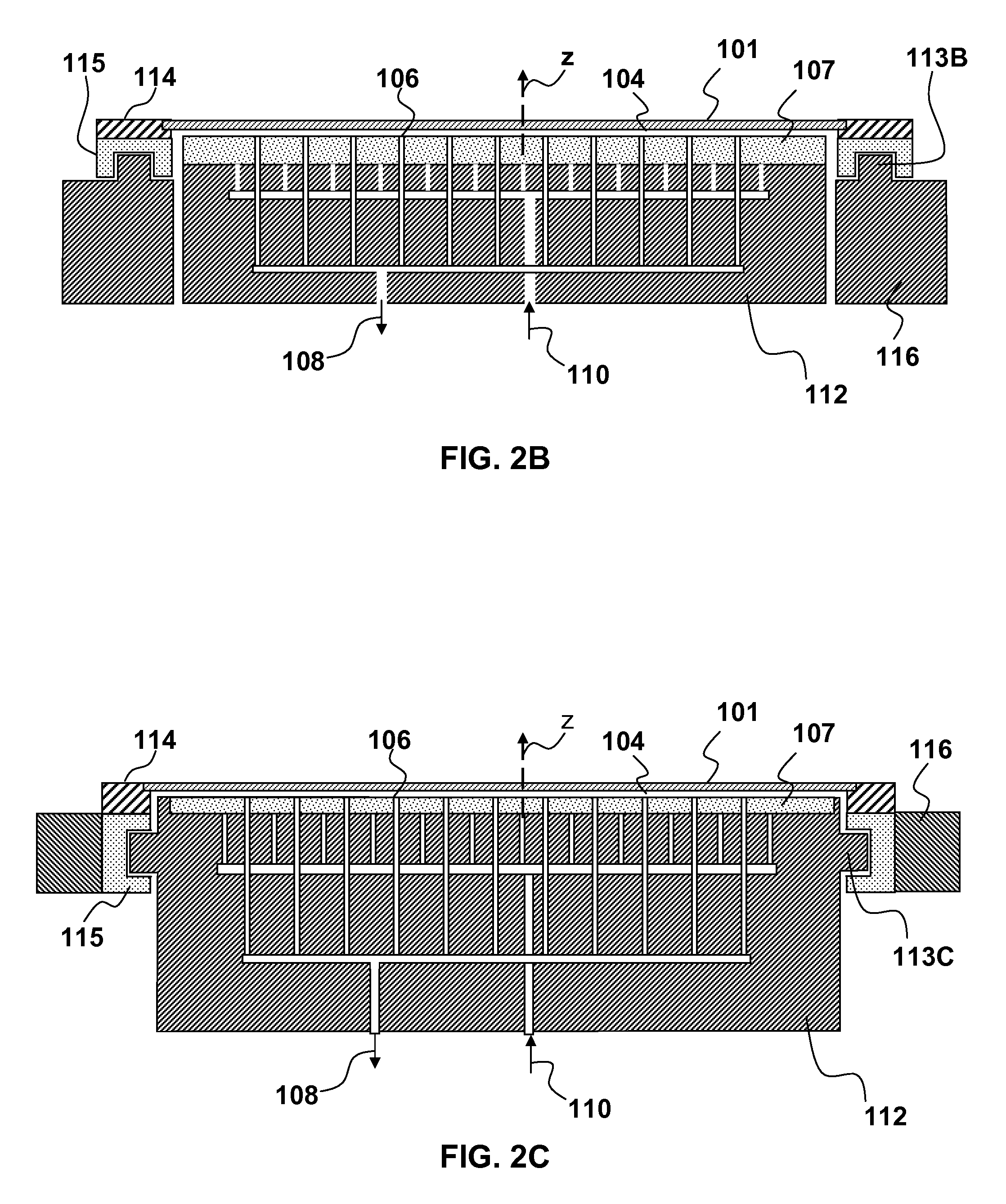
[0016]Recently, vacuum preload air-bearings have been developed. A vacuum preload air bearing generally uses a combination of vacuum and air pressure to lift a load without contacting it. A vacuum preload air-bearing generally comprises a manifold having a central vacuum port surrounded by one or more air pressure ports. Vacuum is applied to the vacuum port and air pressure is provided to the air pressure ports. The combination of vacuum and air pressure provides both a lifting force and an air cushion that keeps the load from contacting the...


PUM


Abstract

Substrate processing method and apparatus are disclosed. The substrate processing apparatus includes a non-contact air bearing chuck with a vacuum preload.

Description

FIELD OF THE INVENTION[0001]This invention generally relates to stabilizing a wafer and more particularly to wafer handling with a vacuum preload air bearing chuck.BACKGROUND OF THE INVENTION[0002]Mechanisms used to examine the surface of a semiconductor wafer commonly use a wafer support known as a handling chuck. Modern semiconductor wafer inspection techniques may entail incrementally inspecting the surface of the wafer with a probe that moves laterally as the wafer rotates, much like a phonograph needle passes over a phonograph record. As may be appreciated, the greater the speed of rotation, the larger the number of sample wafers which may be examined for a given time.[0003]Conventionally the wafer is mounted on an edge handling chuck and supported at three or four points at the edge of the wafer, e.g., using an edge clamp ring that is secured to the chuck. Air passes through a center hole in the chuck and is dispersed to the atmosphere using multiple pressure relief openings i...

Claims


Application Information

Patent Timeline
Patent Type & Authority Patents(United States)
IPC IPC(8): B25B11/00
CPCB25B11/005F16C29/025H01L21/6838H01L21/67784F16C32/0603
Inventor ZHAO, GUOHENGBELYAEV, ALEXANDERWOLTERS, CHRISTIAN H.DOYLE, PAUL ANDREWDANDO, HOWARD W.VAEZ-IRAVANI, MEHDI
Owner KLA TENCOR TECH CORP
Why Eureka
Try Eureka